Steel block dividing and polishing equipment for high-end equipment manufacturing

A technology for equipment and steel blocks, which is applied in the field of steel block dividing and polishing equipment, can solve the problems of labor-consuming, cumbersome steps, danger, etc., and achieves the effect of avoiding the contact between grinding tools and cutting tools, and being simple and convenient to operate.

Active Publication Date: 2021-02-09
SHAOYANG UNIV
View PDF22 Cites 4 Cited by
  • Summary
  • Abstract
  • Description
  • Claims
  • Application Information

AI Technical Summary

Problems solved by technology

[0005] In order to overcome the shortcomings of manual segmentation and polishing, which are dangerous, cumbersome and labor-intensive, the technical problem to be solved is to provide a safe, easy-to-operate and manpower-saving steel block segmentation and polishing equipment for high-end equipment manufacturing

Method used


Image

  • Steel block dividing and polishing equipment for high-end equipment manufacturing
  • Steel block dividing and polishing equipment for high-end equipment manufacturing
  • Steel block dividing and polishing equipment for high-end equipment manufacturing

Examples


Embodiment 1

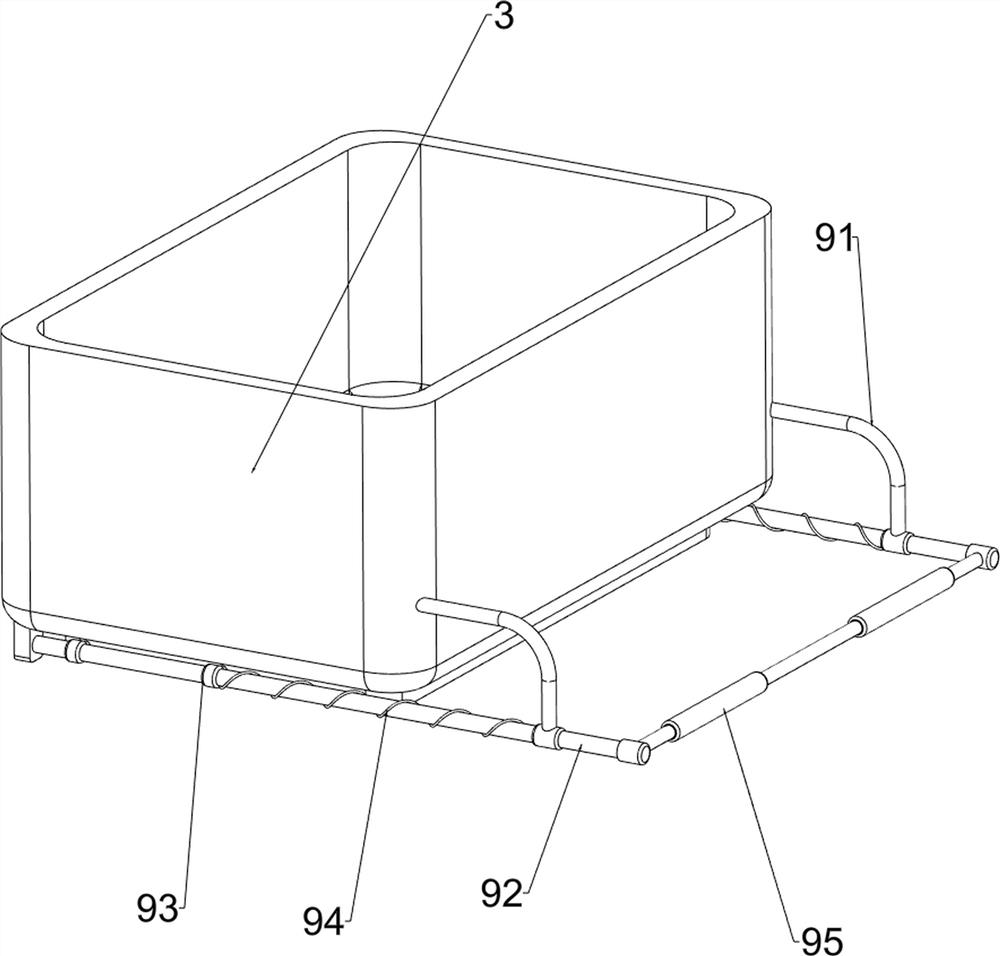
[0068] A steel block split polishing equipment for high-end equipment manufacturing, such as figure 1 and figure 2 As shown, it includes a base plate 1, a heterosexual track 2, a collection frame 3, a laser cutting gun 4, a feeding mechanism 5, and a grinding mechanism 6. The base plate 1 is provided with a heterosexual track 2, and the upper rear side of the base plate 1 is provided with a collection frame 3. A laser cutting gun 4 is connected between the left and right sides of the opposite track 2, and a discharge mechanism 5 is provided on the opposite track 2, and the discharge mechanism 5 is connected with the bottom plate 1 and the collection frame 3, and the middle part of the opposite track 2 is provided with a grinding mechanism 6 .

[0069] Manually dividing and polishing steel blocks is dangerous, the steps are cumbersome and labor-intensive. This equipment can automatically divide and polish steel blocks, which is safe, easy to operate and can save manpower. Th...

Embodiment 2

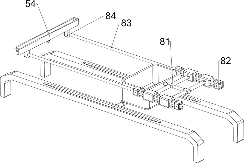
[0071] On the basis of Example 1, such as figure 2 and image 3 As shown, the discharge mechanism 5 includes a pillar 51, a first slide bar 52, a first spring 53, a straight slide rail 54, a second slide bar 55, a second spring 56, a circular post 57, and a first slide sleeve 58. , the third slide bar 59 and the third spring 510, the front middle part of the bottom plate 1 is provided with a pillar 51, the first slide bar 52 is connected between the top of the pillar 51 and the collection frame 3, and a sliding type is provided on the first slide bar 52 The word slide rail 54, the first slide bar 52 is wound with the first spring 53, the front side of the first spring 53 is connected with the word slide rail 54, the rear side of the first spring 53 is connected with the collection frame 3, the left and right sides of the word slide rail 54 Both sides are slidingly provided with a second slide bar 55, and the two second slide bars 55 are all wound with a second spring 56, the...

Embodiment 3

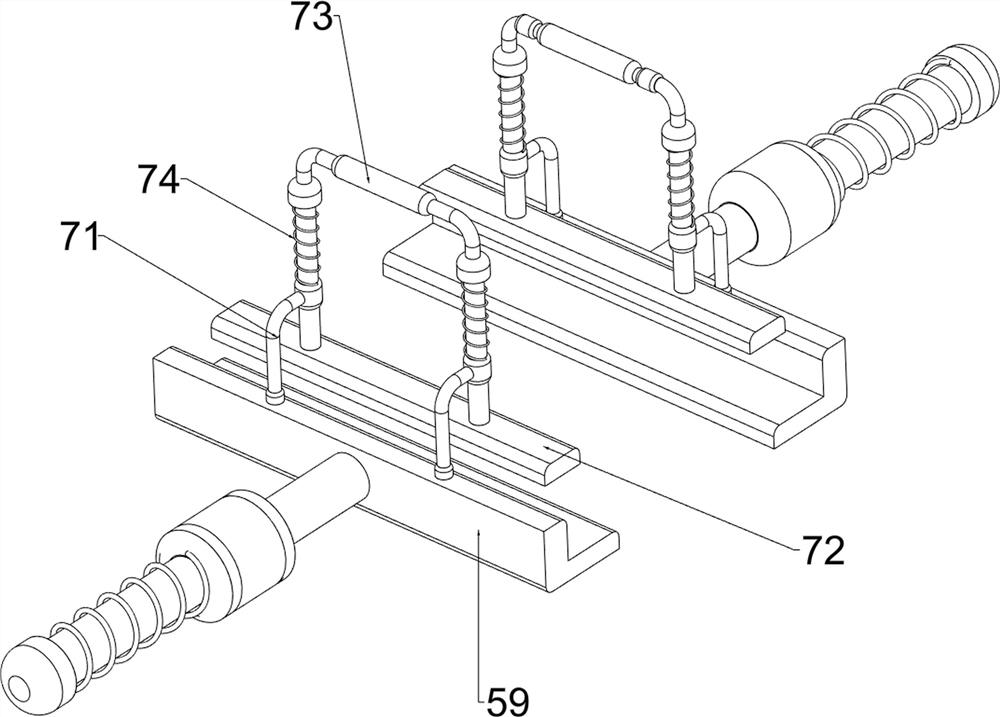
[0076] On the basis of Example 2, such as figure 1 , Figure 4 , Figure 5 , Image 6 and Figure 7 As shown, a clamping mechanism 7 is also included, and the clamping mechanism 7 includes a second sliding sleeve 71, a splint 72, a first pull rod 73 and a fourth spring 74, and two second sliding rods are arranged on the inner side of the top of the third sliding rod 59. Cover 71, the first pull rod 73 is slidably connected between the inner side of the second sliding sleeve 71 on the front and rear sides, the first pull rod 73 on the left and right sides is all wound with a fourth spring 74 on both sides, the top of the fourth spring 74 is connected with The first pull rod 73 is connected, the bottom of the fourth spring 74 is connected with the second sliding sleeve 71 , and the bottoms of the first pull rod 73 on the left and right sides are provided with splints 72 , and the splints 72 cooperate with the third slide bar 59 .

[0077] When the third slide bar 59 moves to...


PUM


Abstract

The invention relates to dividing and polishing equipment, in particular to steel block dividing and polishing equipment for high-end equipment manufacturing. The steel block dividing and polishing equipment for high-end equipment manufacturing is safe, easy to operate and capable of saving manpower. The steel block dividing and polishing equipment for high-end equipment manufacturing comprises abottom plate, a special-shaped rail, a collecting frame, a laser cutting gun, a discharging mechanism and a grinding mechanism. The special-shaped rail is arranged on the bottom plate; the collectingframe is arranged on the bottom plate; the laser cutting gun is arranged on the special-shaped rail; the discharging mechanism is arranged on the special-shaped rail, and the discharging mechanism isconnected with the bottom plate and the collecting frame; and the grinding mechanism is arranged in the middle of the special-shaped rail. A first gear is engaged with a second gear, the first gear rotates to drive the second gear to rotate, so that a grinding rod rotates, when divided steel blocks make contact with the grinding rod, the grinding rod grinds and polishes the steel blocks, the automatic grinding and polishing effect is achieved, and operation is easy and convenient.

Description

technical field [0001] The invention relates to a split polishing device, in particular to a steel block split polishing device used in the manufacture of high-end equipment. Background technique [0002] The high-end equipment manufacturing industry occupies a core position in the industrial chain, and its development level determines the overall competitiveness of the industrial chain. In the process of high-end equipment manufacturing, people need to divide and polish steel blocks. The traditional division and polishing technology is mainly manual operation. Divide the steel block first, and then polish it. The steps are cumbersome and require a lot of manpower. In addition, the traditional technology is manual loading and unloading, which is more dangerous. [0003] Patent application CN210435839U, the publication date is 2020.05.01, discloses a chamfering polishing equipment, including chamfering equipment, first chamfering equipment, second chamfering equipment, chamfe...

Claims


Application Information

Patent Timeline
Patent Type & Authority Applications(China)
IPC IPC(8): B24B7/10B24B41/00B24B27/00B24B41/06B23K26/38
CPCB23K26/38B24B7/10B24B27/0076B24B41/005B24B41/06
Inventor 李颂
Owner SHAOYANG UNIV
Why Eureka
Try Eureka