Welding detection device

A welding detection and sliding joint technology, which is applied in welding equipment, metal processing equipment, manufacturing tools, etc., can solve the problems of single detection method, large X-ray damage to the human body, and difficult adjustment of detection orientation, so as to improve safety and prevent The effect of radiation leakage

Inactive Publication Date: 2017-06-13
盐城中咏投资发展有限公司
View PDF5 Cites 1 Cited by
  • Summary
  • Abstract
  • Description
  • Claims
  • Application Information

AI Technical Summary

Problems solved by technology

[0002] Welding inspection is widely used in welding technology, and it is an important inspection method to check whether the quality of welding products is qualified. It mainly uses the difference in intensity attenuation of the welding part (weld seam) of X-rays to penetrate the inspected item to determine whether there are pores in the welding product. , slag inclusion, incomplete penetration, incomplete fusion and cracks and other quality problems. In the prior art, the detection method for some larger welding products is single, the detection position adjustment is difficult, and many disadvantages such as missed detection often occur, which affect the detection results. At the same time, in the unprotected state, X-rays cause great damage to the human body, and it is impossible to guarantee non-damage operation, which has great disadvantages and cannot meet the existing needs

Method used


Image

  • Welding detection device
  • Welding detection device
  • Welding detection device

Examples


Embodiment Construction

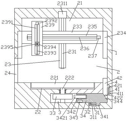
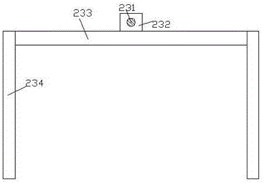
[0020] Such as Figure 1-Figure 5 As shown, a welding detection device of the present invention includes a cabinet 1 with a cavity 2 inside, the top wall of the cavity 2 is provided with a first embedding groove 21, and the bottom wall of the cavity 2 is provided with a There is a second embedding groove 22, and the cabinet body 1 at the bottom of the second embedding groove 22 is provided with a control cavity 3 elongated to the right, and the end of the extension section on the right side of the control cavity 3 is There is a through groove 4 extending upward and penetrating the inner bottom wall of the cabinet body 1, and the rear inner wall of the cavity 2 is provided with a push-up groove extending upward and penetrating into the first embedding groove 21 23. The push-up groove 23 is provided with a first screw-shaped rod 231, and the first screw-shaped rod 231 is connected with the first electric motor 2311, and the first electric motor 2311 is arranged in the first embe...


PUM


Abstract

The invention discloses a welding detection device. The device comprises a cabinet body, wherein the cabinet body is internally provided with a cavity; a first embedding groove is formed in the inner top wall of the cavity; a second embedding groove is formed in the inner bottom wall of the cavity; an operating cavity which extends to the right side is arranged in the cabinet body at the bottom of the second embedding groove; a through groove which extends upwards and penetrates through the inner bottom wall of the cabinet body is formed in the tail end of an extending section of the right side of the operating cavity; a pushing-ascending groove which extends upwards and penetrates into the first embedding groove is formed in the inner wall of the rear side of the cavity; a first screwed rod is arranged in the pushing-ascending groove, and is connected with a first motor; the first motor is arranged in the inner top wall of the first embedding groove and is fixedly connected; a first glidingly connected block which is connected in a thread fit way and is connected with the pushing-ascending groove in a glidingly connected fit way is arranged on the first screwed rod; the front end surface of the first glidingly connected block penetrates into the cavity and is fixedly provided with a cross rod; and glidingly connected plates are equally arranged on the two sides of the cross rod. The device has the advantages of simple structure, convenient operation, wide detection range and high efficiency, leakage of ray is prevented, and detection safety is improved.

Description

technical field [0001] The invention relates to the field of welding technology, in particular to a welding detection device. Background technique [0002] Welding inspection is widely used in welding technology, and it is an important inspection method to check whether the quality of welding products is qualified. It mainly uses the difference in intensity attenuation of the welding part (weld seam) of X-rays to penetrate the inspected item to determine whether there are pores in the welding product. , slag inclusion, incomplete penetration, incomplete fusion and cracks and other quality problems. In the prior art, the detection method for some larger welding products is single, the detection position adjustment is difficult, and many disadvantages such as missed detection often occur, which affect the detection results. At the same time, in the unprotected state, X-rays will cause great damage to the human body, and no damage-free operation cannot be guaranteed, which has ...

Claims


Application Information

Patent Timeline
Patent Type & Authority Applications(China)
IPC IPC(8): B23K31/12
CPCB23K31/125
Inventor 骆剑锋
Owner 盐城中咏投资发展有限公司
Why Eureka
Try Eureka