Grinding equipment with automatic discharge function

An automatic unloading and functional technology, applied in the direction of grinding machine tools, grinding devices, metal processing equipment, etc., can solve the problems of prolonging the wafer grinding processing time, reducing the wafer processing efficiency, increasing the workload of workers, etc., to ensure the grinding effect, The effect of improving processing efficiency and reducing labor load

Active Publication Date: 2018-10-12
重庆晶宇光电科技有限公司
View PDF7 Cites 0 Cited by
  • Summary
  • Abstract
  • Description
  • Claims
  • Application Information

AI Technical Summary

Problems solved by technology

However, the commonly used grinder is not equipped with a wafer blanking mechanism. After the wafer is ground, the worker needs to manually remove the wafer from the workbench. required processing time, thereby reducing wafer processing efficiency

Method used


Image

  • Grinding equipment with automatic discharge function
  • Grinding equipment with automatic discharge function
  • Grinding equipment with automatic discharge function

Examples


Embodiment Construction

[0020] The present invention will be further described in detail below through specific implementations:

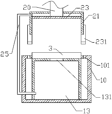
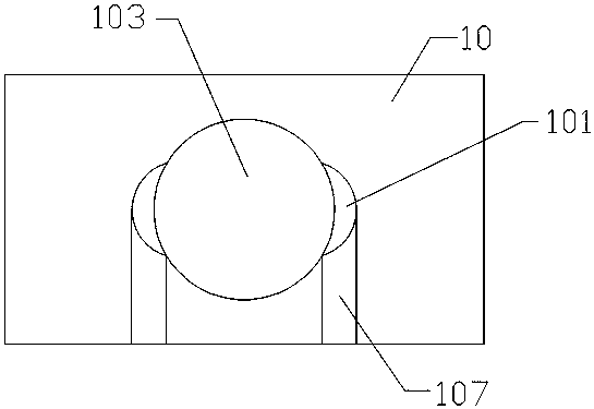
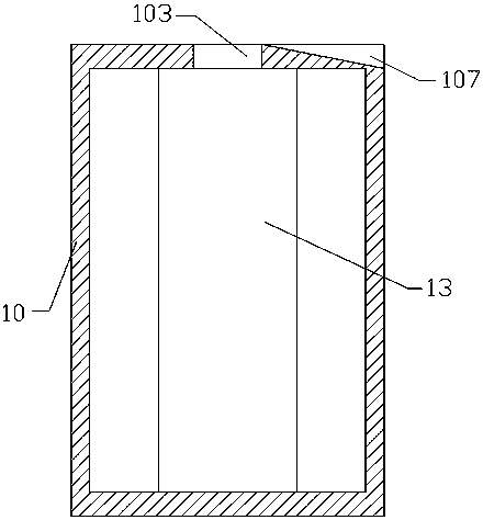
[0021] The reference signs in the drawings of the specification include: processing table 10, placement table 13, suction hole 131, slot 101, placement hole 103, wafer 3, clamping rod 231, connecting rod 235, driving box 21, polishing head 23, The drive rod 20, the air duct 25, and the guide groove 107.

[0022] Such as figure 1 with figure 2 The shown grinding equipment with automatic unloading function includes a processing table 10 for placing a wafer 3 to be ground and a grinding mechanism for grinding the wafer 3. The grinding mechanism is located above the processing table 10, and the grinding mechanism includes a grinding head 23, The driving rod 20 and the driving box 21 that is sleeved on the driving rod 20 and the opening faces downward, the grinding head 23 is slidingly fitted in the driving box 21, the lower end of the driving rod 20 extends into the driving box 2...


PUM


Abstract

The invention relates to the field of manufacturing of optical wafers, in particular to lapping equipment with an automatic material discharging function. The lapping equipment comprises a machining table for placing a wafer to be ground and a lapping mechanism for lapping the wafer, wherein the lapping mechanism is located above the machining table; the lapping mechanism comprises a lapping head, a driving rod and a driving box; the lapping head is matched in the driving box in a sliding manner; the lower end of the driving rod extends into the driving box and is connected with the lapping head; two side surfaces of the driving box are connected with clamping rods in a rotatable manner; a placing table is fixed in a hollow cavity in the machining table; an adsorption hole is formed in the placing table; a placing hole for accommodating the wafer is formed in the top surface of the machining table; two sides of the placing hole communicate with the insertion slots; an air guide pipe is connected between the lapping mechanism and the machining table; the air inlet end of the air guide pipe is located above the lapping head and communicates with the driving box; and the air outlet end of the air guide pipe communicates with the placing table. The invention aims to provide the lapping equipment capable of realizing the automatic discharging operation of the wafer.

Description

Technical field [0001] The invention relates to the field of optical wafer production, in particular to a grinding equipment with an automatic unloading function. Background technique [0002] As a kind of light-transmitting equipment of imaging equipment, wafers need to be polished and polished during processing. The basic technology of wafer grinding is grinding. The planetary motion wafer is continuously ground through the rotation of the grinding plate of the grinder and the abrasive dispersed on the grinding plate to remove the knife marks produced during the slicing process. , The purpose of slicing the damaged layer and controlling the thickness. [0003] The existing polishing machine includes a worktable for placing wafers and a polishing head for polishing the wafers. After the wafers to be polished are first placed on the worktable, the polishing heads polish the wafers placed on the worktable. However, the commonly used grinder does not have a wafer unloading mechanis...

Claims


Application Information

Patent Timeline
Patent Type & Authority Patents(China)
IPC IPC(8): B24B37/10B24B37/30B24B37/34
CPCB24B37/10B24B37/30B24B37/34B24B37/345
Inventor 侯明永
Owner 重庆晶宇光电科技有限公司
Why Eureka
Try Eureka