
Precision reducer

A precision reducer and intermediate meshing technology, applied in the mechanical field, can solve the problems of material fatigue, large volume, expensive price, etc., and achieve the effect of meeting volume requirements, small volume, and long service life

Inactive Publication Date: 2017-06-13
智剑
View PDF6 Cites 3 Cited by
  • Summary
  • Abstract
  • Description
  • Claims
  • Application Information

AI Technical Summary

Problems solved by technology

Most of the reducers used by existing robots use cycloid reducers or harmonic reducers. Cycloid reducers: the structure is more complicated, the price is more expensive, and the volume is relatively large; Using flexible materials, the failure mode is often the fatigue of the material; and the processing and heat treatment of this material are relatively complicated
Therefore, the existing technology cannot provide a reducer with small spacing and long service life, which affects the development of robots.

Method used


Image

  • Precision reducer
  • Precision reducer
  • Precision reducer

Examples


Embodiment 1

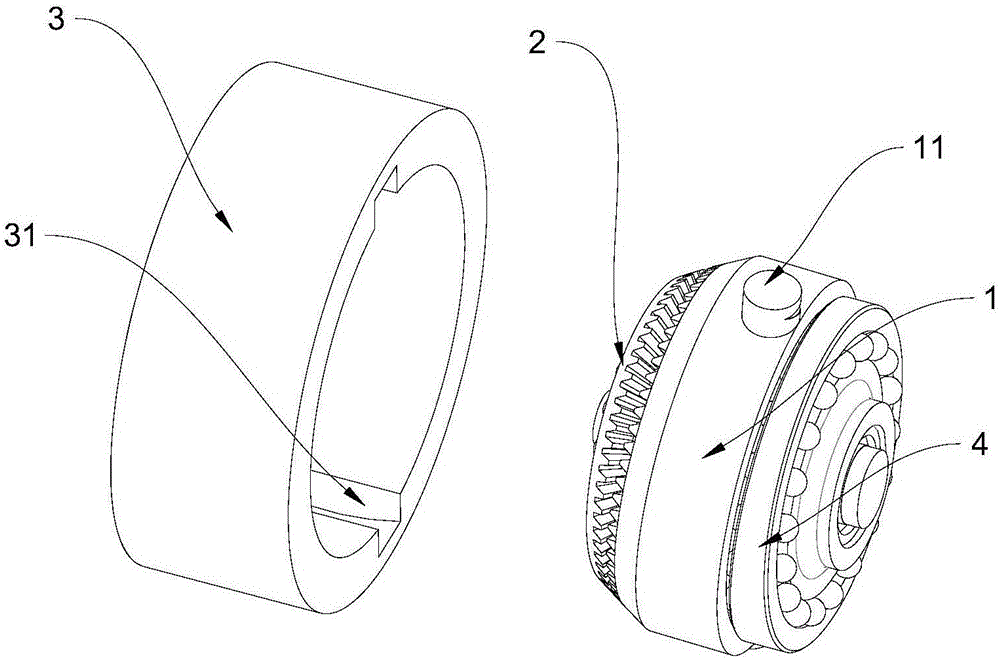
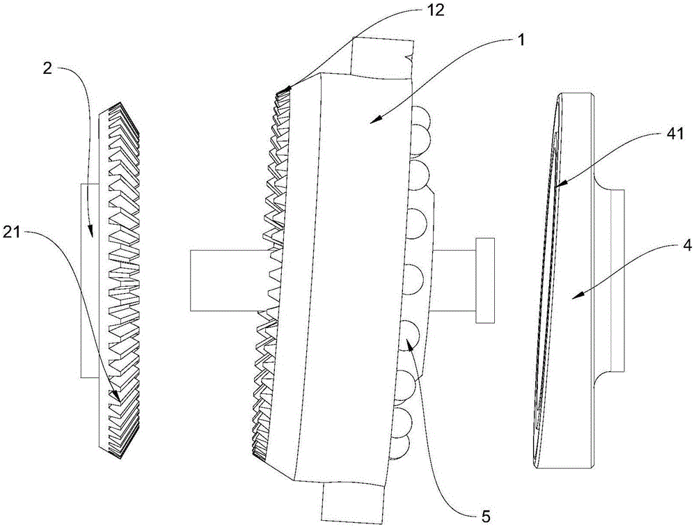
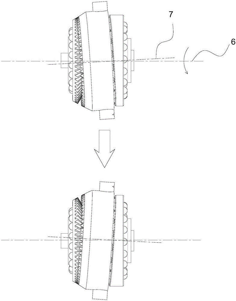
[0029] see Figure 1-Figure 3 , the present invention provides a precision reducer, including a middle meshing disk 1 and an output disk 2, the middle meshing disk 1 meshes with the output disk 2, and the specific meshing method is: the top surface of the middle meshing disk 1 is provided with several The first teeth 12 evenly distributed on the axis 7 of the meshing disc, the second teeth 21 evenly distributed around the axis of the output disc 2 are provided on the bottom surface of the output disc 2, and the meshing between the middle meshing disc 1 and the output disc 2 is the first tooth 12 For meshing with the second teeth 21 , it should be emphasized that there is a difference between the number of teeth of the first teeth 12 and the number of teeth of the second teeth 21 .

[0030] The axis 7 of the middle meshing disk intersects the axis of the output disk 2 at one point, that is to say, there is a certain angle between the axis 7 of the middle meshing disk and the ax...

Embodiment 2

[0043] On the basis of Embodiment 1, Embodiment 2 adds a rotating disk 4, and a mounting slope 41 is provided on one side of the rotating disk 4. The angle interval between the rotation axis 6 of the rotating disk 4 and the mounting slope 41 is [2 °, 90 °), the specific example of the included angle is 10 °, 30 °, 45 °, 60 °, 75 °, 80 °, 85 °, the bottom surface of the middle meshing disc 1 is installed on the installation slope 41 of the rotating disc 4 Above, the rotation axis 6 of the rotating disk 4 is on the same straight line as the axis of the output disk 2, and the axis 7 of the intermediate meshing disk intersects the rotation axis 6 of the rotating disk 4 at a point, and this point is located on the installation slope 41, and the installation slope 41 is provided with a circle of balls 5, and the bottom surface of the middle meshing disc 1 is installed on the installation slope 41 through the balls 5.

[0044] Specifically, the rotating disk 4 rotates around the axis...

Embodiment 3

[0048] On the basis of the second embodiment, the ring of balls 5 in the second embodiment is replaced with a bearing, also to ensure that the rotation of the rotating disk 4 does not drive the rotation of the intermediate meshing disk 1 .


PUM


Abstract

The invention relates to a precision reducer, which belongs to the field of machinery, and includes an intermediate meshing disk and an output disk, the output disk is engaged with the middle meshing disk, and the middle meshing disk moves around the axis of the output disk under the action of external power It performs revolution movement, and during the revolution process of the middle meshing disk, the middle meshing disk does not rotate; there is a difference in the number of teeth between the first teeth on the middle meshing disk and the second teeth on the output disk, and using the two There is a difference in the number of teeth between them, and the oscillating middle meshing disc pushes the output disc to rotate. The invention can prolong the service life of the reducer and control the volume of the reducer.

Description

technical field [0001] The invention provides a precision reducer, which belongs to the field of machinery and is mainly applied to joints of robots. Background technique [0002] The movement of the robot joints is usually driven by the motor to drive the reducer to drive the movement of the corresponding joints. The reducer used by the robot usually needs to have: a large reduction ratio, high precision and high strength. Most of the reducers used by existing robots use cycloid reducers or harmonic reducers. Cycloid reducers: the structure is more complicated, the price is more expensive, and the volume is relatively large; Using flexible materials, the failure mode is often the fatigue of the material; and the processing and heat treatment of this material are relatively complicated. Therefore, the prior art cannot provide a reducer with small spacing and long service life, which affects the development of robots. Contents of the invention [0003] In order to solve t...

Claims


Application Information

Patent Timeline
Patent Type & Authority Applications(China)
IPC IPC(8): B25J17/00B25J9/10
CPCB25J17/00B25J9/1025
Inventor 智剑
Owner 智剑
Learn More