
Belt film heat-seal forming equipment

A thermal synthesis and equipment technology, applied in the direction of flat products, household utensils, and other household utensils, can solve the problems of film stretching, damage to the flatness and tightness of the film, and the difficulty of roller shaft processing, so as to ensure flatness and The effect of tightness

Active Publication Date: 2017-06-13
BOEN SOLAR TECH
View PDF5 Cites 0 Cited by
  • Summary
  • Abstract
  • Description
  • Claims
  • Application Information

AI Technical Summary

Problems solved by technology

[0004] When it is necessary to continuously heat seal the ultra-wide greenhouse film of 6 meters or more, it is correspondingly necessary to use a roller shaft that matches the width of the film to realize the transmission of the film, that is, the length of the roller shaft must also reach 6 meters or more, using the solid roller structure in the integral molding of the existing heat sealing device will cause the quality of the roller to be large, especially the middle part of the roller will bend downward under the influence of its own weight, resulting in The outer peripheral surface of the roller shaft cannot maintain a cylindrical surface. When conveying the ultra-wide greenhouse film, due to the different tension forces on the two sides and the middle of the film, the film will be stretched, resulting in deformation and damage to the film during the conveying process. The flatness and tightness of the film are improved; at the same time, the processing of the roller shaft of 6 meters or more is difficult and the processing cost is high, which further leads to an increase in the cost of the heat sealing device

Method used


Image

  • Belt film heat-seal forming equipment
  • Belt film heat-seal forming equipment
  • Belt film heat-seal forming equipment

Examples


Embodiment 1

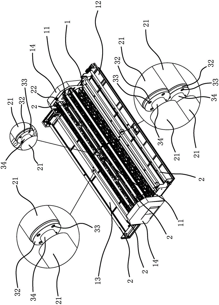
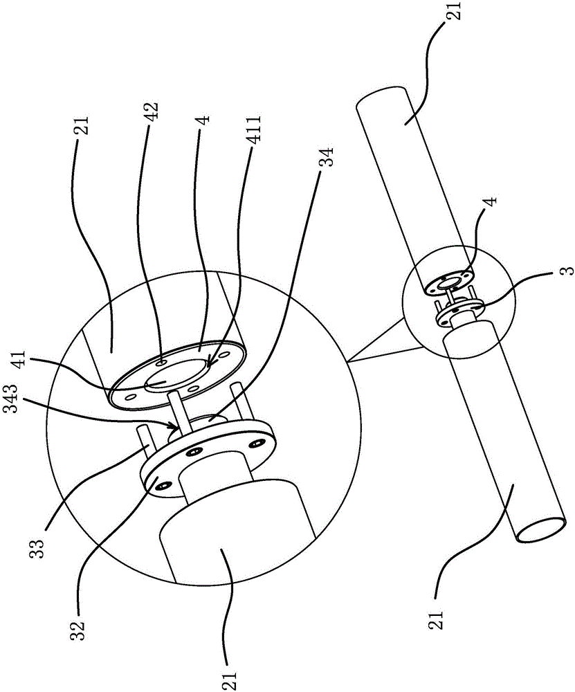
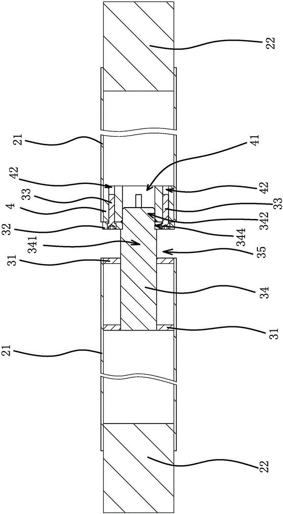
[0027] Such as figure 1 and figure 2 As shown, the heat-synthesizing equipment with film includes a frame 1, a heat-sealing mechanism 11 arranged in the frame 1, and an input mechanism 12 and an output mechanism 13 are respectively arranged on both sides of the frame 1. On the frame 1 and the input mechanism 12 Both the drive roller shaft 2 and the output mechanism 13 are provided with the drive roller shaft 2. The drive roller shaft 2 is supported by the frame seats 14 located at both ends. The drive roller shaft 2 is composed of two axially penetrating hollow shafts 21. One end is plugged and fixed with a solid connecting shaft 22, and the connecting shaft 22 is connected with the corresponding frame base 14, and the other end of one hollow shaft 21 is plugged and fixed with a splice 3, and the other end of the other hollow shaft 21 One end is plugged and fixed with splicing piece 2 4, and splicing piece 1 3 can be plugged and fixed with splicing piece 2 4 so that the two ...

Embodiment 2

[0034] The structure and principle of this embodiment are basically the same as that of Embodiment 1, the difference is that: Figure 4 As shown, the transmission roller shaft 2 is supported by the frame bases 14 located at both ends and the middle part of the transmission roller shaft 2 is supported by a support ring 51. The specific structure is as follows: a bearing 5 is sleeved on the relief section 341, and the width of the bearing 5 is smaller than the gap The width of 35, the inner ring of bearing 5 is fixed with step-off section 341, and the outer ring of bearing 5 is covered with support ring 51, and the diameter of support ring 51 is less than the diameter of hollow shaft 21. The supporting ring 51 can be connected with the frame 1, the supporting ring 51 is fixed relative to the frame 1, the driving roller shaft 2 rotates relative to the supporting ring 51, the outer peripheral surface of the supporting ring 51 does not protrude from the outer peripheral surface of t...

Embodiment 3

[0036] The structure and principle of this embodiment are basically the same as that of Embodiment 1, the difference is that: figure 1 As shown, the transmission roller shaft 2 is only supported by the frame bases 14 located at both ends, the transmission roller shaft 2 is composed of two axially penetrating hollow shafts 21, and one end of the two hollow shafts 21 is plugged and fixed with a solid Connecting shaft 22, the connecting shaft 22 is connected with the corresponding frame seat 14, the other end of one hollow shaft 21 is plugged and fixed with splicing piece 1 3, and the other end of the other hollow shaft 21 is plugged and fixed with splicing piece 2 4 , splicing piece 1 3 can be plugged and fixed with splicing piece 2 4 so that the two hollow shafts 21 are positioned both in the circumferential direction and in the axial direction, and neither splicing piece 1 3 nor splicing piece 2 4 protrudes from the outer peripheral surface of the corresponding hollow shaft 21 ...


PUM


Abstract

The invention provides belt film heat-seal forming equipment and belongs to the technical field of greenhouse film forming. The belt film heat-seal forming equipment solves the technological problems of the high machining cost and the like of existing belt film heat-seal forming equipment. The belt film heat-seal forming equipment comprises a rack and a transmission roll shaft. The transmission roll shaft is supported by rack seats located at the two ends of the rack. The transmission roll shaft is formed by splicing two transversely-through hollow shafts. A solid connecting shaft is fixedly inserted into one end of each hollow shaft. The connecting shafts are correspondingly connected with the rack seats. A first splicing piece is fixedly inserted into the other end of one of the hollow shafts. A second splicing piece is fixedly inserted into the other end of the other hollow shaft. The two hollow shafts are positioned in the peripheral direction and axial direction by fixedly inserting the first splicing piece into the second splicing piece, and both the first splicing piece and the second splicing piece do not protrude out of the peripheral surfaces of the corresponding hollow shafts. The belt film heat-seal forming equipment has the beneficial effects that the flatness and the degree of tightness of ultra-wide type greenhouse films are guaranteed.

Description

technical field [0001] The invention belongs to the technical field of greenhouse film forming, and relates to a heat-synthesizing equipment with film. Background technique [0002] Greenhouse is a frame-covered structure with excellent thermal insulation performance. It is a very important facility in the process of modern agricultural production and has been widely used in agricultural production in most areas of our country. Plastic film is a commonly used material in agricultural greenhouses. In order to facilitate the cultivation of greenhouses, the demand for large-span greenhouses has increased, and the cost requirements have been reduced. It is necessary to improve the greenhouse film into a film, and heat-bond the high-strength polyester tape and the film. Therefore, A heat sealer is often required. [0003] For example, a longitudinal cable-membrane device heat-sealing machine disclosed in Chinese patent literature [Application No.: 201510615648.4] includes: a fra...

Claims


Application Information

Patent Timeline
Patent Type & Authority Applications(China)
IPC IPC(8): B29C65/02B29C65/78B29L7/00
CPCB29C65/02B29C65/7858B29L2007/00
Inventor 甘汉南梅未
Owner BOEN SOLAR TECH
Learn More