Conveying screw device with sealing function and application of conveying screw device

A conveying screw with sealing technology, which is applied in packaging and other directions, can solve the problems of easy leakage and poor discharge, and achieve the effect of reliable sealing, small space occupation and compact structure

Active Publication Date: 2017-06-13
BC P INC CHINA NAT PETROLEUM CORP +1
View PDF7 Cites 3 Cited by
  • Summary
  • Abstract
  • Description
  • Claims
  • Application Information

AI Technical Summary

Problems solved by technology

[0003] The purpose of the present invention is to overcome the problems of easy leakage and poor discharge when the traditional screw transports the material in the pressurized airtight container to the normal pressure.

Method used


Image

  • Conveying screw device with sealing function and application of conveying screw device
  • Conveying screw device with sealing function and application of conveying screw device
  • Conveying screw device with sealing function and application of conveying screw device

Examples


Embodiment 1

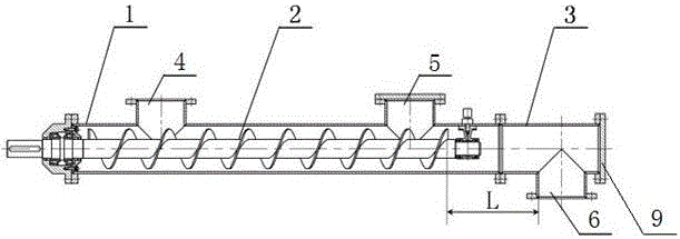
[0017] This example provides figure 1 The shown conveying screw device with sealing function includes a screw outer cylinder 1 and an additional outer cylinder 3. The screw outer cylinder 1 and the additional outer cylinder 3 are connected by bolts, and the wall of the additional outer cylinder 3 A discharge port 6 with an opening downward is provided on the top, a screw shaft 2 is installed in the spiral outer cylinder 1, and a feed port 4 and a feed port 5 with an upward opening are provided on the wall of the spiral outer cylinder 1, and the feed port 4 is set On the side close to the power end of the screw shaft 2 , the feeding port 5 is located near the connection between the screw outer cylinder 1 and the additional outer cylinder 3 .

[0018] figure 1 Shown is the structural diagram of the conveying screw device with sealing function of 25°≤material repose angle≤45°, the working process of the conveying screw device is:

[0019] Before use, connect the feed port 4 to ...

Embodiment 2

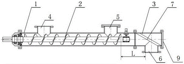
[0022] On the basis of Example 1, such as figure 2 As shown, the additional outer cylinder 3 is provided with an anti-blocking baffle 7, and the anti-blocking baffle 7 is fixed on the inner wall of the additional outer cylinder 3 in an oblique shape, with its inclined surface facing the side of the screw shaft 2, and the discharge port 6 is located below the inclined surface.

[0023] figure 2 Shown is the structural diagram of a conveying screw device with a sealing function with a material repose angle ≥ 45°. The working process of the conveying screw device is:

[0024] Before use, connect the feed port 4 to the discharge port of the pressure vessel, open the feed port 5, add a sufficient amount of plugging material, block the feed port 5, and when the conveying screw is working, the material in the feed port 4 is on the screw shaft. Under the action of 2, the material moves backwards, and the angle of repose of the material is ≥ 45°. Since there is a certain distance L...

Embodiment 3

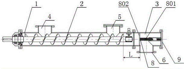
[0026] On the basis of Embodiment 1, the additional outer cylinder 3 is provided with a sealing aid 8, the auxiliary sealing member 8 is composed of a spring 801 and a baffle 802, and one end of the spring 801 is fixed on the bottom plate 9 of the additional outer cylinder 3 , and the other end is fixedly connected with the board surface of the baffle plate 802 .

[0027] image 3 Shown is the structural diagram of the conveying screw device with sealing function with material repose angle ≤ 25°. The working process of the conveying screw device is:

[0028] Before use, connect the feed port 4 to the discharge port of the pressure vessel, open the feed port 5, add a sufficient amount of plugging material, block the feed port 5, and when the conveying screw is working, the material in the feed port 4 is on the screw shaft. Under the action of 2, the material moves backward, the angle of repose of the material is ≤25°, the material moves towards the additional outer cylinder 3 ...


PUM


Abstract

The invention provides a conveying screw device with a sealing function and an application of the conveying screw device. The conveying screw device comprises an outer screw barrel, a screw shaft and an additional outer barrel, wherein the outer screw barrel and the additional outer barrel are communicated through a bolt; a discharging port with a downward opening is formed in the wall of the additional outer barrel, the screw shaft is mounted in the outer screw barrel, a feeding port and a charging port which have upward openings are formed in the wall of the outer screw barrel, the feeding port is formed in one side close to a power end of the screw shaft, and the charging port is close to the connection position of the outer screw barrel and the additional outer barrel. According to the conveying screw device with the sealing function, during operation of a conveying screw, a material conveyed by the conveying screw forms a material sealing section between a blade at the tail end of the screw shaft and the outlet. The conveying screw device with the sealing function can convey the material in a sealed manner without an additional sealing device and has the characteristics of compact structure, reliable blocking and small occupation space.

Description

technical field [0001] The invention relates to a conveying screw structure in the fields of oil field, construction, chemical industry, metallurgy and medicine, in particular to a conveying screw device with sealing function and its application. Background technique [0002] The inlet and outlet of the traditional conveying screw are mostly at normal pressure. In the process of using the traditional screw to transport the material from the pressurized airtight container to the normal pressure, when the feed inlet is insufficient, it is easy to cause gas leakage in the airtight container. Contents of the invention [0003] The purpose of the invention is to overcome the problems of easy leakage and poor material discharge when the traditional screw transports the material in the pressurized airtight container to the normal pressure. [0004] For this reason, the present invention provides a conveying screw device with a sealing function, which includes a screw outer cylin...

Claims


Application Information

Patent Timeline
Patent Type & Authority Applications(China)
IPC IPC(8): B65G33/14B65G33/24
CPCB65G33/14B65G33/24
Inventor 王玉陈在君李前春胡东锋方晓军王思凡权银虎张岄谭欢安全成
Owner BC P INC CHINA NAT PETROLEUM CORP
Why Eureka
Try Eureka