Flue gas treatment system for ceramic production

A flue gas treatment system, ceramic technology, applied in the direction of gas treatment, combustion product treatment, combustion methods, etc., can solve the problems of rising system operating costs, more power, consumption, etc., and achieve simple structure, low operating cost, and reduced operation cost effect

Pending Publication Date: 2018-11-30
FOSHAN SAINDI ENVIRONMENTAL PROTECTION TECH CO LTD
View PDF0 Cites 3 Cited by
  • Summary
  • Abstract
  • Description
  • Claims
  • Application Information

AI Technical Summary

Problems solved by technology

Although this design can achieve the purpose, it needs to consume more power, resulting in an increase in the operating cost of the system

Method used


Image

  • Flue gas treatment system for ceramic production
  • Flue gas treatment system for ceramic production

Examples


Embodiment Construction

[0040] The technical solutions of the present invention will be further described below in conjunction with the accompanying drawings and through specific implementation methods.

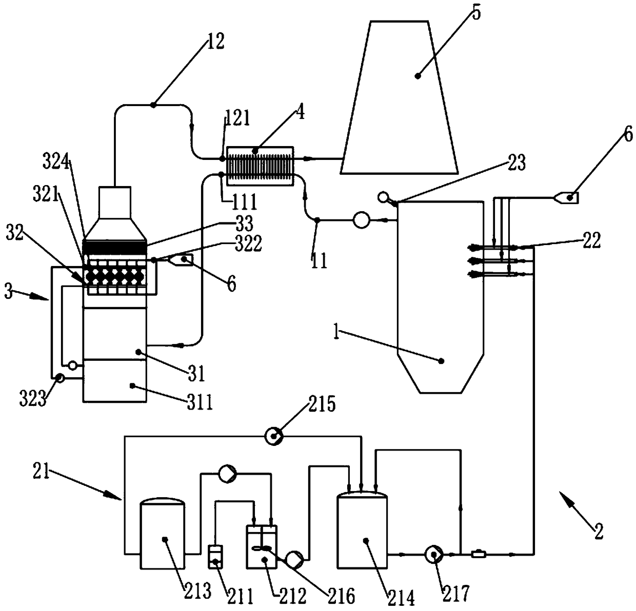
[0041] A flue gas treatment system for ceramic production in this embodiment includes a boiler 1, a denitrification system 2, a desulfurization system 3, a heat exchanger 4, a chimney 5 and a gas source 6, the boiler 1, the desulfurization system 2 and the Said chimney 5 is piped in turn;

[0042] The denitrification system 2 includes a reductant preparation module 21 and a denitrification injection head 22, the input end of the denitrification injection head 22 is connected with the output end of the reductant preparation module 21, and the denitrification injection head 22 is connected to the inner surface of the boiler 1. Cavity correspondence;

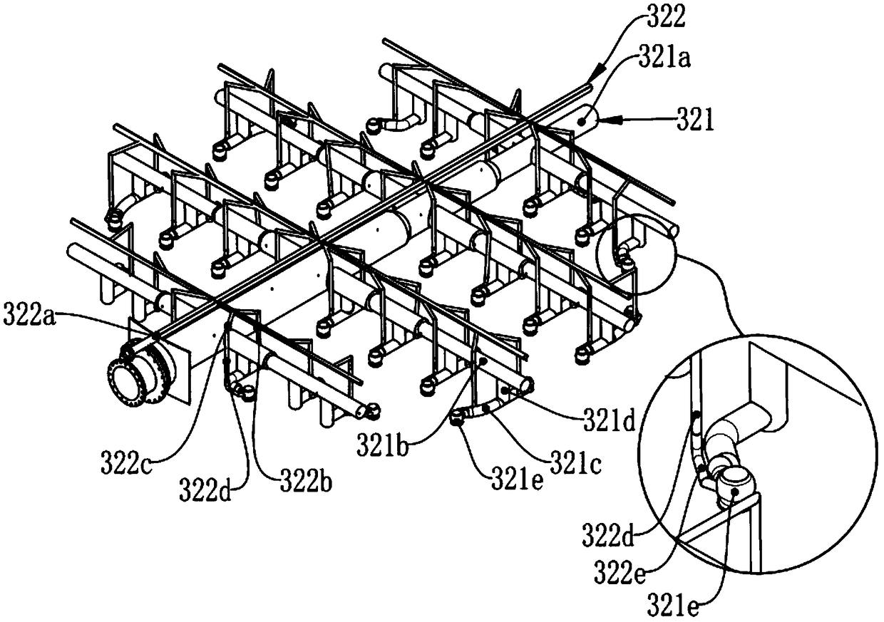
[0043] The desulfurization system 3 includes a spray module 32 and a desulfurization tower 31. The spray module 32 includes a spray layer 321, an air p...


PUM


Abstract

The present invention discloses a flue gas treatment system for ceramic production. The flue gas treatment system comprises a boiler, a denitration system, a desulfurization system, a heat exchanger,a chimney and a gas source; the boiler, desulfurization system, and chimney are sequentially connected by pipelines; flue gas is desulfurized by the desulfurization system and denitrated by the denitration system; denitration spray heads spray a reducing agent prepared in a reducing agent preparation module into the boiler to remove nitrogen oxides in the flue gas generated by the boiler; the heatexchanger is arranged in a flue inlet heat exchange section and a flue outlet heat exchange section; heat of raw flue gas not subjected to desulfurization by a desulfurization tower is transferred tonet flue gas subjected to the desulfurization by the desulfurization tower via the heat exchanger; liquid water carried by the net flue gas is converted into gaseous water, thereby achieving an effect of eliminating white smoke. The flue gas treatment system organically combines the three purification devices for the denitrification, desulfurization and white smoke elimination together, is simplein structure, low in operation cost and good in desulfurization and denitration effects, and reduces environmental impacts in the ceramic production.

Description

technical field [0001] The invention relates to the technical field of environmental protection, in particular to a flue gas treatment system for ceramic production. Background technique [0002] In the production of ceramics, a large amount of industrial waste gas will be generated. These waste gases include sulfur, nitrogen and other pollutants. Therefore, these industrial waste gases need to be treated. In addition, due to the low temperature and high humidity of the flue gas, the flue gas discharged from the chimney Mixing with cold air will cause the water vapor in the flue gas to condense to form white smoke, which will affect the appearance of the environment. [0003] In the power industry, the selective non-catalytic reduction denitrification system is generally used to denitrify the flue gas. Due to the difference in the concentration and content of nitrogen oxides produced in the ceramic manufacturing industry, the concentration of nitrogen oxides produced in the ...

Claims


Application Information

Patent Timeline
Patent Type & Authority Applications(China)
IPC IPC(8): B01D53/75B01D53/50B01D53/56B01D53/79B01D53/80F23J15/00F23J15/04F23J15/08
CPCB01D53/75B01D53/50B01D53/56B01D53/79B01D53/80B01D2251/2067B01D2258/0283F23J15/003F23J15/006F23J15/04F23J15/08F23J2215/10F23J2215/20F23J2219/40F23J2219/50
Inventor 黄建起王建军黄逸
Owner FOSHAN SAINDI ENVIRONMENTAL PROTECTION TECH CO LTD
Why Eureka
Try Eureka