A long strip in-situ cutting conveying system

A conveying system and long strip technology, which is applied in the direction of sending objects, transportation and packaging, thin material processing, etc., can solve the problems of speed limitation and efficiency, and achieve the prevention of secondary offset, fast loading operation, and improved processing Accuracy and productivity effects

Active Publication Date: 2018-10-26
SHANGHAI KINBIO TECH
View PDF10 Cites 0 Cited by
  • Summary
  • Abstract
  • Description
  • Claims
  • Application Information

AI Technical Summary

Problems solved by technology

[0004] There must be reciprocating motion in the three-dimensional direction of the manipulator. If the image recognition of the position of the test paper is required during this reciprocating motion, there must be a speed limit. At present, the machines on the market generally stay at 20-30 strips per minute, and it is difficult to improve
Compared with manual operation, such a manipulator card loading system has no advantage in efficiency

Method used


Image

  • A long strip in-situ cutting conveying system
  • A long strip in-situ cutting conveying system
  • A long strip in-situ cutting conveying system

Examples


Embodiment Construction

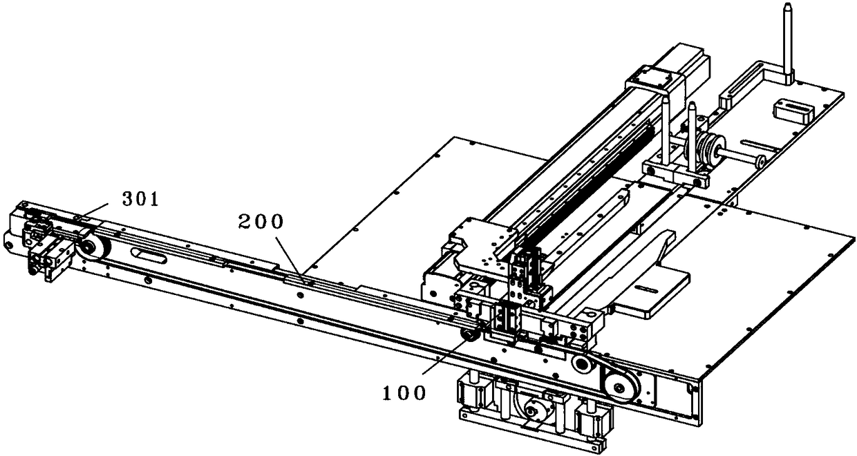
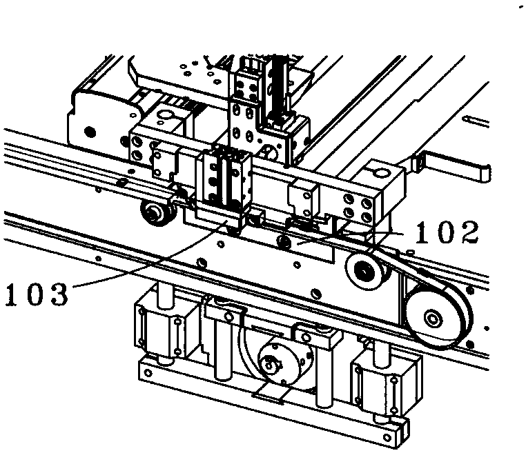
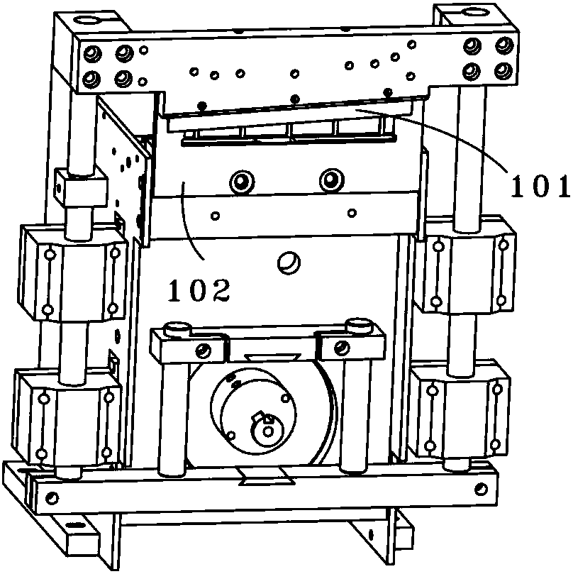
[0053] In order to make the above objects, features and advantages of the present invention more obvious and comprehensible, specific implementations of the present invention will be described in detail below in conjunction with the accompanying drawings.

[0054] In the following description, a lot of specific details are set forth in order to fully understand the present invention, but the present invention can also be implemented in other ways different from those described here, and those skilled in the art can do it without departing from the meaning of the present invention. By analogy, the present invention is therefore not limited to the specific examples disclosed below.

[0055] Secondly, the present invention is described in detail in combination with schematic diagrams. When describing the embodiments of the present invention in detail, for the convenience of explanation, the cross-sectional view showing the device structure will not be partially enlarged according ...


PUM


Abstract

The invention discloses a long strip in-situ cutting and conveying system. The long strip in-situ cutting and conveying system comprises a long strip cutting device, a first conveying device and a long strip carrier; long strips stay to be located on the long strip carrier after being conveyed for a certain distance by using the first conveying device. The long strip in-situ cutting and conveying system has the advantages that the cut long strips are accurately pressed and located in a physical manner by using the long strip cutting device and a long strip locating device; through being longitudinally located, transversely located and vacuum-adsorbed to the long strip carrier, the transversely conveyed long strips can be located in an adjusting manner and can be adsorbed to the long strip carrier so as to prevent secondary offset and improve the assembling accuracy; through reasonable mechanical locating, a visual identification system is eliminated in the working station, so that the long strips are assembled and fixed more conveniently and rapidly, and the production efficiency is enhanced.

Description

technical field [0001] The invention relates to the technical field of strip cutting and clamping, in particular to a long strip in-situ cutting conveying system. Background technique [0002] At present, there are two cutting production processes for biomedical diagnostic test strips: one is rolling cutting, and the other is chopping. In the conventional cutting production, the strip-shaped test strips for diagnosis and testing are cut into long strips (for example: length x width is 60x 4mm), and the test strips go down from the cutting position along the lower knife surface and the guide plate. Slide down and fall into a container, then manually put the finished test strip into the bottom card of the plastic card box, then manually cover the face card of the card box, and finally press the bottom card and the face card by a card press machine tight. This method of manually assembling the test paper cartridge is not only inefficient, but also cannot guarantee the quality...

Claims


Application Information

Patent Timeline
Patent Type & Authority Patents(China)
IPC IPC(8): B65H35/00B65H35/06B65H29/16B65H29/24B65H29/52
CPCB65H29/16B65H29/242B65H29/52B65H35/008B65H35/06B65H2406/3223B65H2406/366
Inventor 周中人周春乐刘波姜杰
Owner SHANGHAI KINBIO TECH
Why Eureka
Try Eureka