
Structure for oil-gas separation of engine bearing chamber and axial ventilation of multiple bearing chambers

A bearing cavity and engine technology, applied in engine components, engine lubrication, bearing components, etc., can solve problems affecting the reliability of the whole machine, increasing the complexity and weight of the whole machine, affecting the performance of high-performance gas turbines and aero-engines, etc. To achieve the effect of efficient separation and efficient axial ventilation

Active Publication Date: 2017-06-13
INST OF ENGINEERING THERMOPHYSICS - CHINESE ACAD OF SCI
View PDF5 Cites 13 Cited by
  • Summary
  • Abstract
  • Description
  • Claims
  • Application Information

AI Technical Summary

Problems solved by technology

Obviously, the external piping required by these systems and the need for a separate oil mist separator will not only affect the reliability of the whole machine, but also significantly increase the complexity and weight of the whole machine, and ultimately affect the performance of high-performance gas turbines and aero engines. Further performance improvements

Method used


Image

  • Structure for oil-gas separation of engine bearing chamber and axial ventilation of multiple bearing chambers
  • Structure for oil-gas separation of engine bearing chamber and axial ventilation of multiple bearing chambers

Examples


Embodiment Construction

[0022] In order to make the object, technical solution and advantages of the present invention clearer, the present invention will be further described in detail below in conjunction with examples, so that the advantages and features of the present invention can be more easily understood by those skilled in the art. It should be noted that the following examples are for explaining the present invention and the present invention is not limited to the following examples. In fact, it will be apparent to those skilled in the art that various modifications and variations can be made in the present invention without departing from the scope or spirit of the invention. For example, features illustrated or described as part of one embodiment can be used with another embodiment to yield a still further embodiment. Therefore, it is intended that the present invention cover such modifications and variations as come within the scope of the appended claims and their equivalents.

[0023] ...


PUM


Abstract

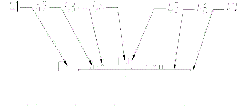
The invention relates to a structure for oil-gas separation of an engine bearing chamber and axial ventilation of multiple bearing chambers. An oil-gas separation component assembled on a high-speed rotating shaft is arranged in the bearing chamber, and the peripheral surface of he oil-gas separation component is provided with main oil throw-off hole, an auxiliary throw-off hole and a plurality of oil breaking grooves formed in a circumferential direction; a vent pipe base is arranged in the high-speed rotating shaft and communicated with the oil-gas separation component in a downstream bearing chamber through a vent line, so as to achieve bearing chamber axial ventilation of multiple bearing chambers. By using the structure, the axial ventilation among different bearing chambers can be effectively achieved, the chamber pressure balance of high-speed rotating bearing chambers of an engine and a ground gas turbine engine can be achieved more efficiently, the proportion of oil mist in gas flow during air ventilation is reduced, the ventilation effect of the bearing chamber is improved and the engine oil mist separation requirement of an oil mist separator outside an engine is reduced. The structure has an important engineering application value for the ground gas turbine engine or an aircraft engine with further reduced lubricating oil consumption.

Description

technical field [0001] The invention relates to a bearing cavity oil-gas separation and multi-bearing cavity axial ventilation structure used in the fields of gas turbines, aero-engines, etc., using the design of the main / auxiliary oil throwing hole, oil cut-off groove and oil accumulation groove of the structure to realize the oil and gas in the bearing cavity Separation, use the ventilation pipe seat and ventilation pipeline to realize the shaft ventilation of different bearing chambers. Background technique [0002] The separation of lubricating oil and gas in high-speed rotating bearing chambers and the chamber pressure equalization of multiple bearing chambers are engineering problems of great practical significance in the fields of gas turbines and aeroengines. [0003] In the previous structural design of gas turbines and aero-engines, the separation of oil and gas in the bearing cavity was achieved by the oil mist injection pipeline outside the main body and the oil ...

Claims


Application Information

Patent Timeline
Patent Type & Authority Applications(China)
IPC IPC(8): F02C7/06F16C3/02F16C35/04
CPCF02C7/06F16C3/02F16C35/04
Inventor 杜强刘军王沛柳光杨晓洁徐庆宗刘红蕊
Owner INST OF ENGINEERING THERMOPHYSICS - CHINESE ACAD OF SCI
Learn More