
Compressor discharge components and compressors

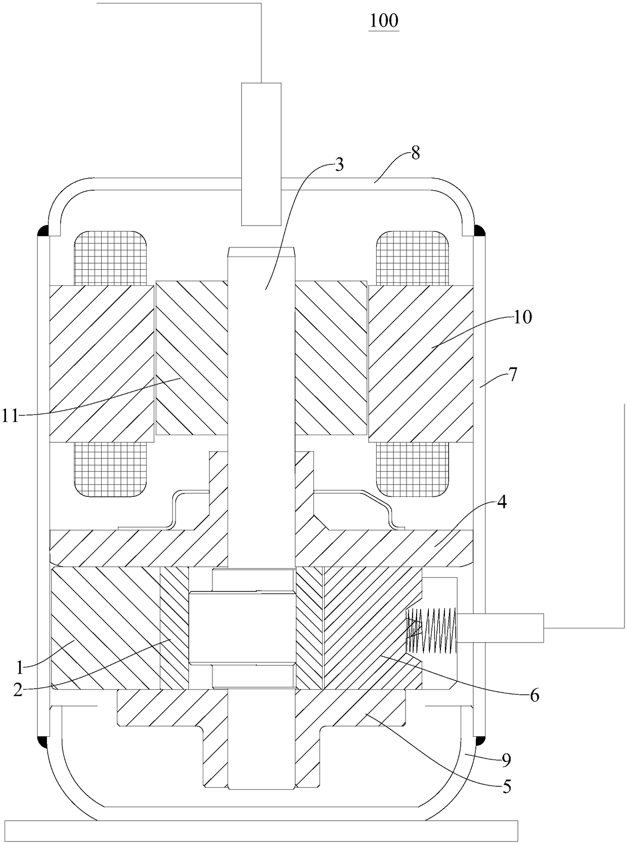
A compressor and component technology, applied in the field of compressors, can solve the problems of easy deformation of the exhaust valve seat, unfavorable compressor efficiency, gas eddy current loss, etc., and achieve the effects of reducing deformation, improving efficiency, and reducing gas eddy current state

Active Publication Date: 2018-11-13
GUANGDONG MEIZHI COMPRESSOR
View PDF7 Cites 0 Cited by
  • Summary
  • Abstract
  • Description
  • Claims
  • Application Information

AI Technical Summary

Problems solved by technology

In the related art, the area of ​​the groove is relatively large, so that the exhaust valve seat is easily deformed. In addition, after the compressed gas is discharged from the exhaust hole, it flows out from the exhaust passage, and the compressed gas will form a gas vortex between the grooves, resulting in gas Eddy current loss is not conducive to improving the efficiency of the compressor, and there is room for improvement

Method used


Image

  • Compressor discharge components and compressors
  • Compressor discharge components and compressors
  • Compressor discharge components and compressors

Examples


Embodiment Construction

[0029] Embodiments of the present invention are described in detail below, examples of which are shown in the drawings, wherein the same or similar reference numerals designate the same or similar elements or elements having the same or similar functions throughout. The embodiments described below by referring to the figures are exemplary and are intended to explain the present invention and should not be construed as limiting the present invention.

[0030] In the description of this specification, descriptions with reference to the terms "one embodiment", "some embodiments", "example", "specific examples", or "some examples" mean that specific features described in connection with the embodiment or example , structure, material or characteristic is included in at least one embodiment or example of the present invention. In this specification, the schematic representations of the above terms are not necessarily directed to the same embodiment or example. Furthermore, the des...


PUM


Abstract

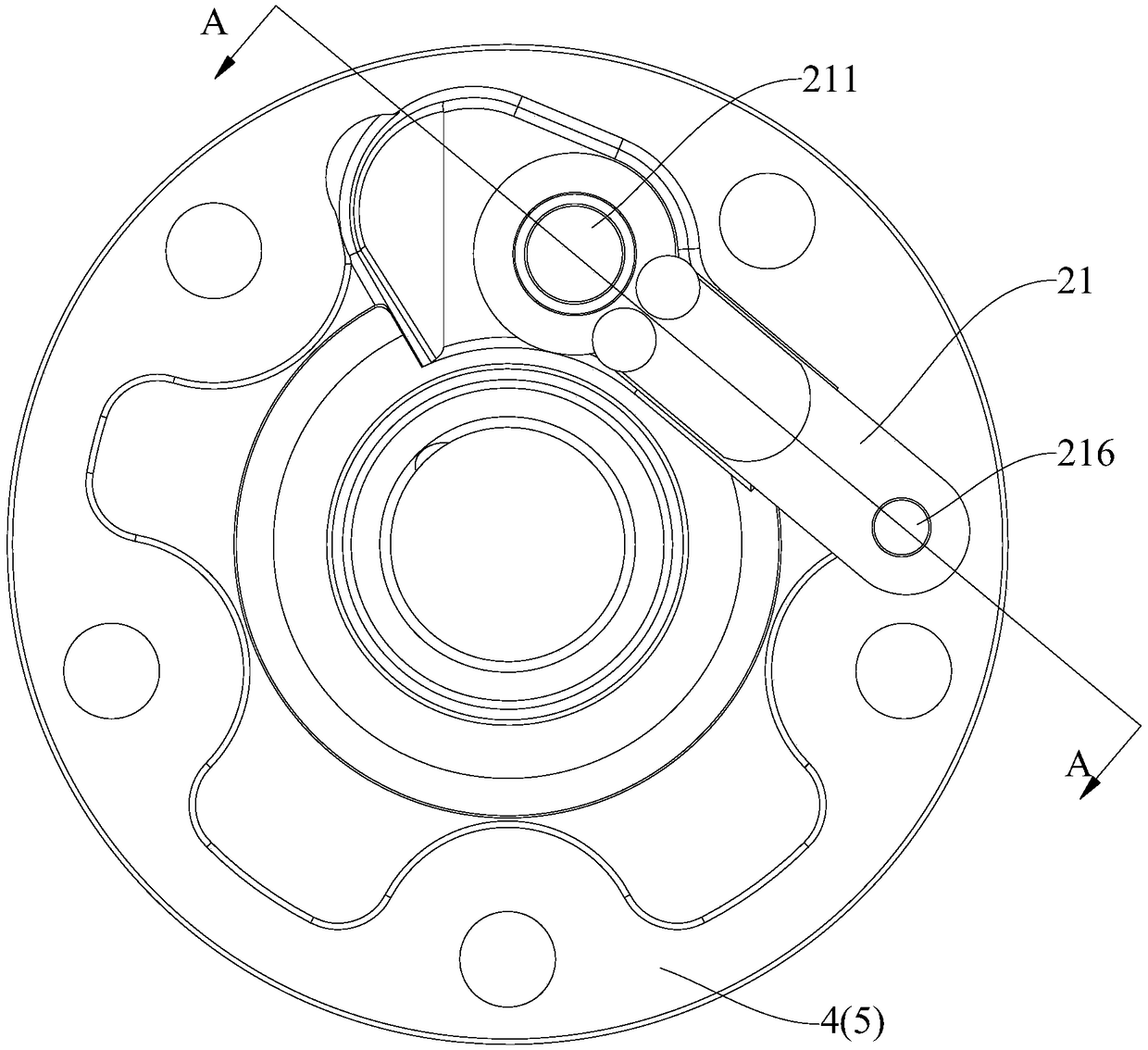
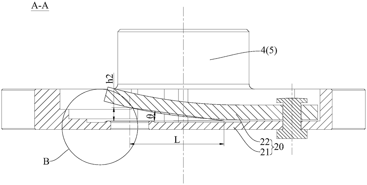
The invention discloses an exhaust assembly of a compressor and the compressor, the exhaust assembly of the compressor includes an exhaust valve seat and an exhaust valve plate, the exhaust valve seat is provided with an exhaust hole, the bottom wall of the exhaust valve seat is provided with a boss and an escrape, the boss surrounds the exhaust hole, the escrape surrounds the boss, the exhaust valve plate is connected with the exhaust valve seat, and is electively attached to the boss, the height of the boss is h0, the depth of the escrape is h1, the radial distance from the side wall of the escrape to the top point of the boss is Delta R, the limitation opening angle is theta, wherein 0<=h1<= Delta R * Tan(theta)+ h0. The exhaust assembly of the compressor can reduce the area of a thinnest region of the exhaust valve seat by defining of multiple-place dimension relationship of the escrape so as to reduce bearing deformation, and meanwhile by limiting of the height of an exhaust channel first step, gas vortex state caused by a refrigerant can be reduced, exhaust losses in the compressor can be reduced, and the efficiency of the compressor is improved.

Description

technical field [0001] The invention belongs to the technical field of compressor manufacturing, and in particular relates to a compressor exhaust assembly and a compressor with the exhaust assembly. Background technique [0002] When processing the exhaust hole of the compressor, it is necessary to reserve a space for the undercut groove. A groove between the tables, which is the weakest area of ​​rigidity. In the related art, the area of ​​the groove is relatively large, so that the exhaust valve seat is easily deformed. In addition, after the compressed gas is discharged from the exhaust hole, it flows out from the exhaust channel, and the compressed gas will form a gas vortex between the grooves, resulting in gas The eddy current loss is not conducive to improving the efficiency of the compressor, and there is room for improvement. Contents of the invention [0003] The present invention aims to solve one of the technical problems in the related art at least to a cer...

Claims


Application Information

Patent Timeline
Patent Type & Authority Patents(China)
IPC IPC(8): F04C29/00F04C29/12
CPCF04C29/00F04C29/12
Inventor 陈中贵
Owner GUANGDONG MEIZHI COMPRESSOR
Learn More