An electronically controlled single pump solenoid valve drive circuit and its control method

A technology of solenoid valve drive and single pump, applied in the direction of program control, computer control, general control system, etc., can solve the problems of serious resistance temperature drift, many operational amplifier circuits, and easy to be interfered, and achieve good output linearity and response The effect of less time and less working noise

Inactive Publication Date: 2019-01-08
JIANGSU UNIV
View PDF4 Cites 0 Cited by
  • Summary
  • Abstract
  • Description
  • Claims
  • Application Information

AI Technical Summary

Problems solved by technology

The resistance sampling method has certain advantages, but its disadvantages are also obvious, mainly slow response speed, more operational amplifier circuits, easy to be interfered, and serious temperature drift of the resistance, etc.

Method used


Image

  • An electronically controlled single pump solenoid valve drive circuit and its control method
  • An electronically controlled single pump solenoid valve drive circuit and its control method
  • An electronically controlled single pump solenoid valve drive circuit and its control method

Examples


Embodiment

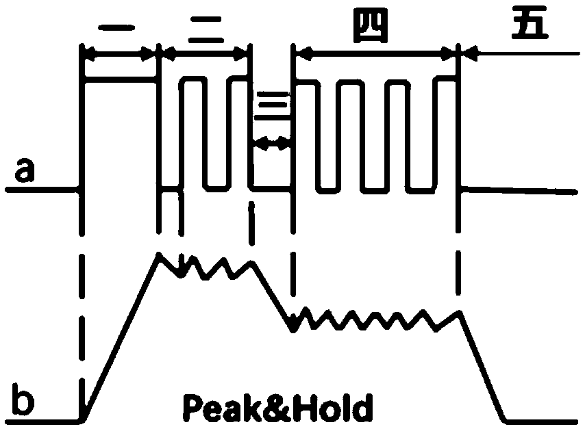
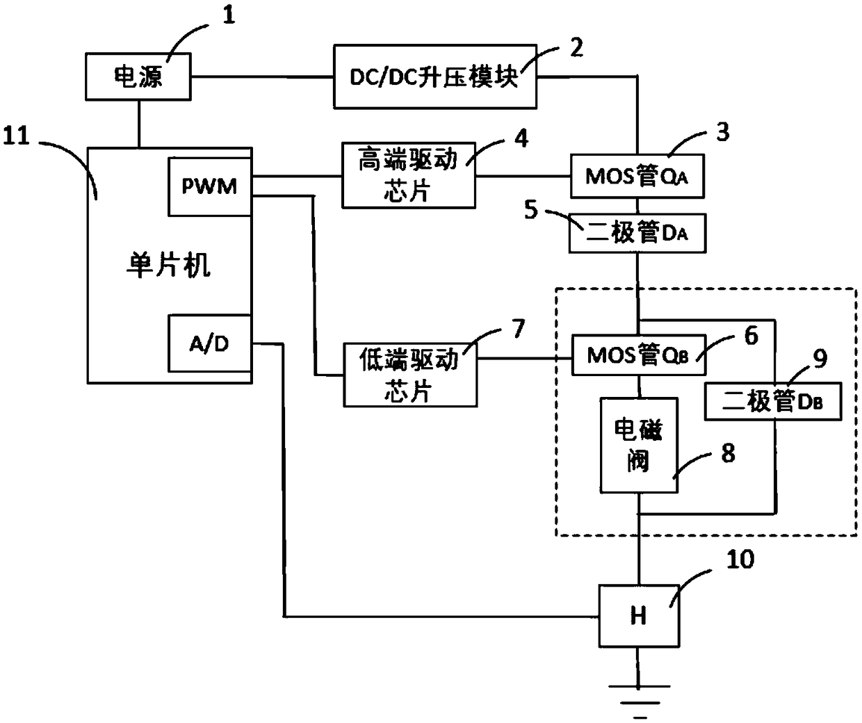
[0027] figure 1 The solenoid valve of the electronically controlled unit pump is shown in the Peak&Hold drive mode, which is divided into five stages: the first stage that needs to supply a large voltage to make the solenoid valve close quickly, the second stage that maintains the peak voltage so that the valve can quickly seat, and the peak The third stage of the transition from voltage to low voltage, the fourth stage of low voltage maintenance to maintain the closed state of the solenoid valve, and the fifth stage of rapid discharge; in the second and fourth stages, it is necessary to cooperate with Hall current sensors to accurately control voltage fluctuations, Cooperate in the fifth stage figure 2 The bleeder circuit in ( figure 2 The dotted line in the middle) realizes the rapid discharge of the solenoid valve.

[0028] figure 2 Shown is the solenoid valve driving circuit of the present invention, including a power supply 1, a DC / DC boost module 2, and a MOS tube ...


PUM


Abstract

The invention discloses an electromagnetic valve driving circuit of an electronic unit pump and a control method thereof, and belongs to the technical field of engine electronic control. The driving circuit comprises a power source, a DC / DC boosting module, a MOS tube QA, a high-end driving chip, a diode DA, a MOS tube QB, a low-end driving chip, an electromagnetic valve, a diode DB, a hall current sensor and a single chip; the MOS tube QA is controlled under a high-end control signal output by the PWM module of the single chip, and matched with a current feedback signal output by the single chip PWM module, so as to modulate the circuit driving voltage; the MOS tube QB is controlled by a low-end control signal output by the single chip PWM module, so as to control the circuit on-off, set up a follow current loop and realize rapid flow discharge. The driving circuit applies the hall current sensor, and has the advantages of few response times, small temperature drift, good output linearity and high durability, and others; the driving circuit matched control method can reduce the on-off frequency of the MOS tube QA, and reduce the circuit working noise.

Description

technical field [0001] The invention belongs to the technical field of engine electronic control, in particular, the invention relates to an electronically controlled unit pump solenoid valve drive circuit and a control method thereof. Background technique [0002] The problem of environmental pollution has become an urgent problem that has plagued the economic development of countries all over the world and improved people's living environment in recent years, especially in developing countries, where environmental problems are particularly prominent. Therefore, the governments of various countries have urged relevant manufacturers to upgrade the technology of existing products by tightening emission regulations for passenger cars and non-road engines. The electronically controlled unit pump system has a higher injection pressure, which can meet the requirements of existing emission regulations and reduce emissions. my country is a major producer of internal combustion eng...

Claims


Application Information

Patent Timeline
Patent Type & Authority Patents(China)
IPC IPC(8): F16K31/06G05B19/042
CPCF16K31/0675G05B19/0423
Inventor 李捷辉胡立毛功平张隆基刘婧韩业扬朱璠冷易凌
Owner JIANGSU UNIV
Why Eureka
Try Eureka