Terminal flashlight structure and mobile terminal
A flashlight and terminal technology, which is applied in the electronic field, can solve problems such as poor heat dissipation, and achieve the effects of avoiding shortened life, reducing the overall temperature rise of the terminal, and lowering the temperature
- Summary
- Abstract
- Description
- Claims
- Application Information
AI Technical Summary
Problems solved by technology
Method used
Image

Examples
no. 1 example
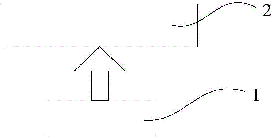
[0021] refer to figure 2 , 3 As shown, the terminal flashlight structure of the embodiment of the present invention includes: a flashlight 1; a heat-absorbing container 2 arranged on the heat dissipation path of the flashlight 1, and the heat-absorbing container 2 is filled with a heat-absorbing substance with a specific heat capacity greater than a preset threshold.
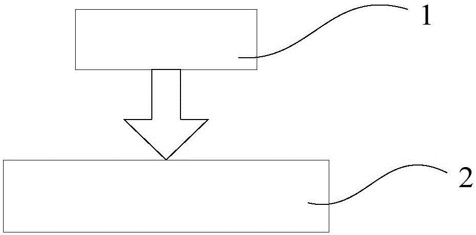
[0022] Here, the heat-absorbing container 2 can be arranged on the heat dissipation path above the flash lamp 1, such as figure 2 As shown, the heat-absorbing container 2 can also be arranged on the heat dissipation path under the flash lamp 1, such as image 3 shown.
[0023] Among them, the preset threshold can be set according to requirements, such as 2×10 3 J / (kg·℃) or 3×10 3 J / (kg·°C). By setting a preset threshold, an endothermic substance with a larger specific heat capacity is selected.
[0024] Preferably, the endothermic substance is pure water. The common substance with larger specific heat c...
no. 2 example
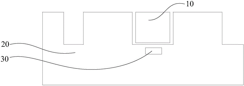
[0029] refer to Figure 4 As shown, the terminal flashlight structure of the embodiment of the present invention includes: a flashlight 1; a heat-absorbing container disposed on the heat dissipation path of the flashlight 1, and the heat-absorbing container is filled with a heat-absorbing substance with a specific heat capacity greater than a preset threshold. The heat-absorbing container includes an optical lens 21 arranged on the heat dissipation path above the flash lamp 1 , and the optical lens 21 includes a cavity 211 inside, and the heat-absorbing substance is filled in the cavity 211 .
[0030] Here, the optical lens 21 can be a Fresnel lens (also known as a threaded lens), which is mainly used for focusing light, that is, the light emitted by the flashlight 1 converges toward the front of the object to be photographed. The optical lens 21 includes a cavity 211 inside, and the cavity 211 is equipped with a heat-absorbing substance with a large specific heat capacity, wh...
no. 3 example
[0039] refer to Figure 6As shown, the terminal flashlight structure of the embodiment of the present invention includes: a flashlight 1; a heat-absorbing container disposed on the heat dissipation path of the flashlight 1, and the heat-absorbing container is filled with a heat-absorbing substance with a specific heat capacity greater than a preset threshold. The heat-absorbing container includes a copper tube arranged on the heat dissipation path under the flash lamp 1, and the heat-absorbing substance is housed in the copper tube.
[0040] Here, the copper material on the surface of the copper tube has a good heat conduction effect, and a heat-absorbing substance with a large specific heat capacity is installed inside the copper tube, which can quickly absorb the instantaneous high junction temperature of the flash lamp.
[0041] Optionally, the copper pipe is a flat copper pipe. The flat copper tube is under the flash, which can have a larger contact area with the flash, s...
PUM
 Abstract
Description
Claims
Application Information
 - R&D Engineer
- R&D Manager
- IP Professional
- Industry Leading Data Capabilities
- Powerful AI technology
- Patent DNA Extraction
Browse by: Latest US Patents, China's latest patents, Technical Efficacy Thesaurus, Application Domain, Technology Topic.
© 2024 PatSnap. All rights reserved.Legal|Privacy policy|Modern Slavery Act Transparency Statement|Sitemap