Fuel oil nozzle

A technology of fuel nozzles and nozzles, applied in combustion chambers, combustion methods, combustion equipment, etc., can solve problems such as high emissions, difficulty in ensuring combustion efficiency, insufficient premixing of gas and air, etc., and achieve the effect of ensuring combustion efficiency

Inactive Publication Date: 2017-06-13
SOUTH UNIVERSITY OF SCIENCE AND TECHNOLOGY OF CHINA
View PDF6 Cites 5 Cited by
  • Summary
  • Abstract
  • Description
  • Claims
  • Application Information

AI Technical Summary

Problems solved by technology

[0003] The premixing of gas and air in traditional fuel nozzles is not sufficient, the combustion efficiency is difficult to guarantee, and the NO x , CO emissions are also higher

Method used


Image

  • Fuel oil nozzle
  • Fuel oil nozzle

Examples


Embodiment Construction

[0010] The present invention will be further described below in conjunction with the description of the drawings and specific embodiments.

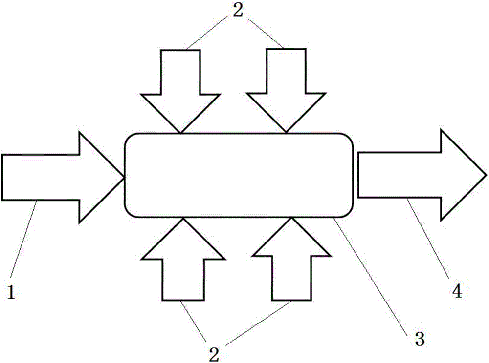
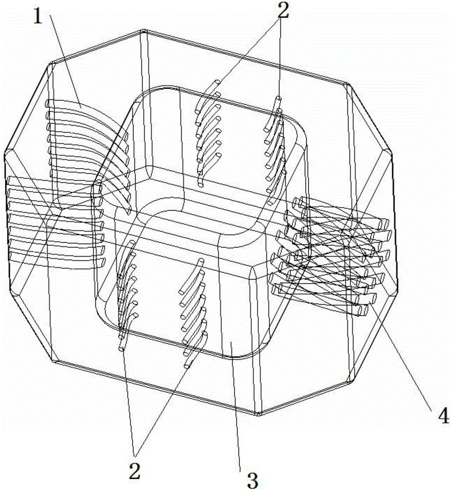
[0011] Such as Figure 1 to Figure 2 As shown, a fuel nozzle includes a fuel pipe 1, an air pipe 2, a mixing area 3 and a mixture nozzle 4, wherein the output ends of the fuel pipe 1 and the air pipe 2 are respectively connected to the input of the mixing area 3 The output end of the mixing zone 3 communicates with the input end of the mixed gas nozzle 4 .

[0012] The fuel nozzle is integrally formed using 3D printing technology.

[0013] The shape and arrangement direction of the fuel pipes 1 are not restricted, and can be designed according to the requirements of the flow field in the mixing zone 3 .

[0014] The size of the fuel pipe 1 is not restricted, and can be designed according to the requirements of the mixing ratio.

[0015] The shape and arrangement direction of the air pipes 2 are not restricted, and can be designed accor...


PUM


Abstract

The invention provides a fuel oil nozzle. The fuel oil nozzle comprises a fuel pipe, air pipes, a mixing area and a mixed gas spraying pipe. The output ends of the fuel pipe and the air pipes communicate with the input end of the mixing area, and the output end of the mixing area communicates with the input end of the mixed gas spraying pipe. The fuel oil nozzle has the beneficial effects that adequate premixing of fuel gas and air can be achieved, and discharging of NOx, CO and the like is effectively reduced while burning efficiency is guaranteed.

Description

technical field [0001] The invention relates to an aero-engine, in particular to a fuel nozzle. Background technique [0002] Fuel and oxygen (or air) are pre-mixed into a uniform mixture. This flammable mixture is called premixed gas. The process of ignition and combustion of the premixed gas in the burner is called premixed combustion. Premixed combustion fuel and oxygen have been fully mixed in the burner before combustion. It is another typical combustion method relative to diffusion combustion. According to whether the content of premixed oxidant can make the fuel burn completely, it can be divided into two types: partial premixed combustion and complete premixed combustion. Additive manufacturing technology refers to a scientific and technological system that directly manufactures parts driven by three-dimensional data of parts based on the principle of discrete accumulation. Based on different classification principles and understanding methods, additive manufactur...

Claims


Application Information

Patent Timeline
Patent Type & Authority Applications(China)
IPC IPC(8): F23R3/28
CPCF23R3/28
Inventor 韩品连张坤
Owner SOUTH UNIVERSITY OF SCIENCE AND TECHNOLOGY OF CHINA
Why Eureka
Try Eureka