Automatic dropwise adding reaction device

A dropwise reaction, automatic technology, applied in chemical/physical/physical-chemical nozzle reactors, chemical/physical/physical-chemical processes, chemical instruments and methods, etc. Problems such as low safety performance, to achieve the effect of small transformation impact, reduced response time, and simple installation

Pending Publication Date: 2022-08-02
上海替末流体技术有限公司
View PDF6 Cites 0 Cited by
  • Summary
  • Abstract
  • Description
  • Claims
  • Application Information

AI Technical Summary

Problems solved by technology

[0003] In the prior art, the dripping reaction process is mainly divided into two processes: dripping and full reaction. The dropping reaction is often accompanied by high heat release, so a high-level tank is required for metered dripping. At present, the dripping operation of most enterprises is still at a standstill. In the purely manual state, the operator needs to observe the liquid level of the high level tank, and slowly open the drip valve according to experience to drip at a constant flow rate. If the operator does not operate according to the specification during the dripping process, a safety accident will occur
At the same time, the solution added dropwise reaches the surface of the solution in the reactor, and due to the slow accumulation, part of the reaction is violent, resulting in accidents such as agglomeration and detonation.
[0004] The dripping sampling device in the prior art is too simple and has low safety performance. The dripping still needs to manually control the valve to control the constant flow rate, which greatly increases the safety hazard and it is difficult to control the constant flow rate. Uneven surface, resulting in some violent reactions and prone to implosion

Method used


Image

  • Automatic dropwise adding reaction device

Examples


Embodiment Construction

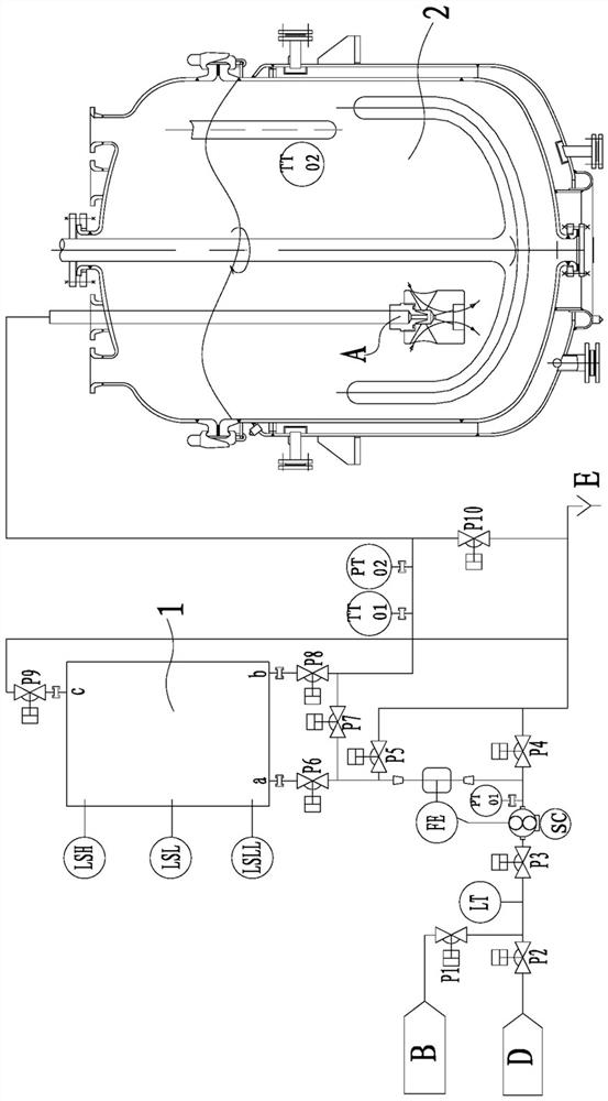
[0042] The present invention will be further described below with reference to the accompanying drawings and embodiments.

[0043] refer to figure 1 , the present invention includes a bubble trap box 1 and a reactor 2.

[0044] The bubble trap box 1 is provided with a high liquid level switch LSH in the upper part, a low liquid level switch LSL in the middle, and a low and low liquid level switch LSLL in the lower part. The high liquid level switch LSH, the low liquid level switch LSL, and the low and low liquid level switch LSLL are connected with a programmable logic controller (PLC) with electrical signals.

[0045] Described reactor 2 is placed with atomizing nozzle A, this atomizing nozzle A is connected with the input port of reactor 2 through pipelines, and this atomizing nozzle A is placed in the inner groove of reactor 2 agitators, and is placed in the below the liquid level.

[0046] A temperature sensor TT02 is also installed in the reactor 2, and the temperature...


PUM


Abstract

An automatic dripping reaction device comprises a bubble trap box and a reaction kettle, and a liquid level switch is arranged on the bubble trap box and electrically connected with a PLC (programmable logic controller). An atomizing nozzle and a temperature sensor are arranged in the reaction kettle; and the temperature sensor and the low-pressure fluid conveyor are connected with a PLC (Programmable Logic Controller). An upper input port of the bubble trap box is connected with an alkali liquor output port through a pneumatic control valve, a mass flow meter, a pressure and liquid level sensor, a low-pressure fluid conveyor and the like; and the mass flow meter is also electrically connected with the PLC. And an output port of the bubble trap box is connected with the atomizing nozzle through the pneumatic control valve and the temperature and pressure sensor. And the bubble trap exhaust port is connected with the exhaust port through a pneumatic control valve. Automatic control is adopted, so that manual dropwise adding is not needed, the dropwise adding amount is constant and controllable, the reaction is uniform and complete, reaction impurities are reduced, and potential safety hazards in the aspects of operation and reaction are solved.

Description

technical field [0001] The invention relates to a device suitable for a dripping process system in the field of chemical equipment, in particular to an automatic dripping reaction device. Background technique [0002] As one of the main chemical reaction production processes, the dropwise addition reaction is mainly used in the conditions of high exotherm and the need to control the reaction conditions smoothly. [0003] In the prior art, the dripping reaction process is mainly divided into two processes: dripping and full reaction, and the dripping reaction is often accompanied by high exothermic heat, so it is necessary to measure the dripping of the high-level tank, and the dripping operation of most enterprises still stays at present. In the purely manual state, the operator needs to observe the liquid level in the high-level tank, and slowly open the dripping valve according to experience and drip at a constant flow rate. If the operator does not operate in accordance w...

Claims


Application Information

Patent Timeline
Patent Type & Authority Applications(China)
IPC IPC(8): B01J19/26B01J19/00
CPCB01J19/26B01J19/0006B01J2219/00162B01J2219/00058B01J2219/00182B01J2219/00184
Inventor 孙念柏荣陈福亮
Owner 上海替末流体技术有限公司
Why Eureka
Try Eureka