
Evaporator flow path structure, evaporator, air conditioner indoor unit and air conditioner

A technology for evaporators and air conditioners, applied to evaporators/condensers, air conditioning systems, refrigerators, etc., can solve the problems of increasing the wind resistance of the back pipe, affecting the performance of the whole machine, and affecting the appearance of the room, etc., to reduce the single cycle stroke , Improve user experience and avoid the effect of overall volume

Inactive Publication Date: 2017-06-13
WUHAN REFRIGERATION EQUIP OF MIDEA GROUP +1
View PDF6 Cites 3 Cited by
  • Summary
  • Abstract
  • Description
  • Claims
  • Application Information

AI Technical Summary

Problems solved by technology

[0002] In the related art, the heat exchanger of the split wall-mounted room air conditioner usually adopts a two-fold, three-fold or multi-fold design. If the system configuration is optimal and the flow path design is optimal, it still cannot reach the design. When the cooling capacity target or the cooling capacity needs to be increased, the performance target of larger cooling capacity is generally achieved by expanding the structural size of the indoor unit and increasing the length of the heat exchanger, that is, increasing the area of ​​the heat exchanger and the circulating air volume of the indoor unit. Therefore, if you want to develop a product with double or higher cooling capacity, then the size of the indoor unit needs to be adjusted, which will increase the cost of the mold and related costs. At the same time, the increase in size will also affect The beauty of the room and takes up more space in the room
[0003] At present, the existing scheme to increase the cooling capacity of the air conditioner is to achieve the required cooling capacity by improving the heat exchange efficiency of the heat exchanger. The pressure loss of the refrigerant is relatively large, resulting in relatively low heat transfer efficiency, especially the low cooling capacity. The longer the flow path, the greater the flow resistance. As the flow velocity in the tube decreases, the heat transfer rate decreases, and it is easy to cause refrigerant bias flow , making it difficult to effectively exchange heat. The pressure loss of the three-inlet and three-outlet flow path evaporator is relatively small, and the heat exchange efficiency is relatively high. However, if the flow path uniformity design is unreasonable, the refrigerant between each path of the heat exchanger will be improperly distributed. In the case of uniformity, the uneven flow will cause a large temperature difference in the flow, which will affect the performance of the whole machine
[0004] In addition to the above solutions, there are also solutions using back pipes. For example, the back or front of the evaporator is used to increase the heat exchange area to meet the corresponding cooling capacity requirements, but the back pipe will increase the size of the back pipe. The air resistance on the side will reduce the circulating air volume of the indoor unit, which will affect the heat exchange efficiency of the evaporator. At the same time, if the air distribution behind the back pipe is uneven, there will be related reliability problems such as condensation or water leakage.

Method used


Image

  • Evaporator flow path structure, evaporator, air conditioner indoor unit and air conditioner
  • Evaporator flow path structure, evaporator, air conditioner indoor unit and air conditioner
  • Evaporator flow path structure, evaporator, air conditioner indoor unit and air conditioner

Examples


Embodiment Construction

[0040] In order to understand the above-mentioned purpose, features and advantages of the present invention more clearly, the present invention will be further described in detail below in conjunction with the accompanying drawings and specific embodiments. It should be noted that, in the case of no conflict, the embodiments of the present application and the features in the embodiments can be combined with each other.

[0041] In the following description, many specific details are set forth in order to fully understand the present invention. However, the present invention can also be implemented in other ways different from those described here. Therefore, the protection scope of the present invention is not limited by the specific details disclosed below. EXAMPLE LIMITATIONS.

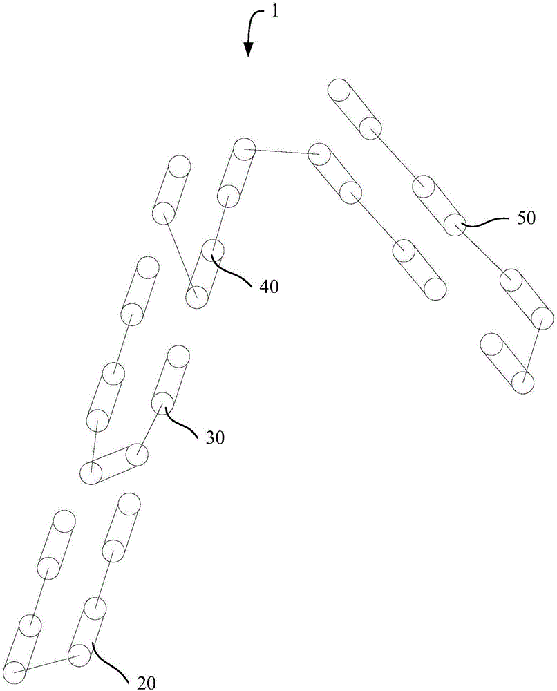
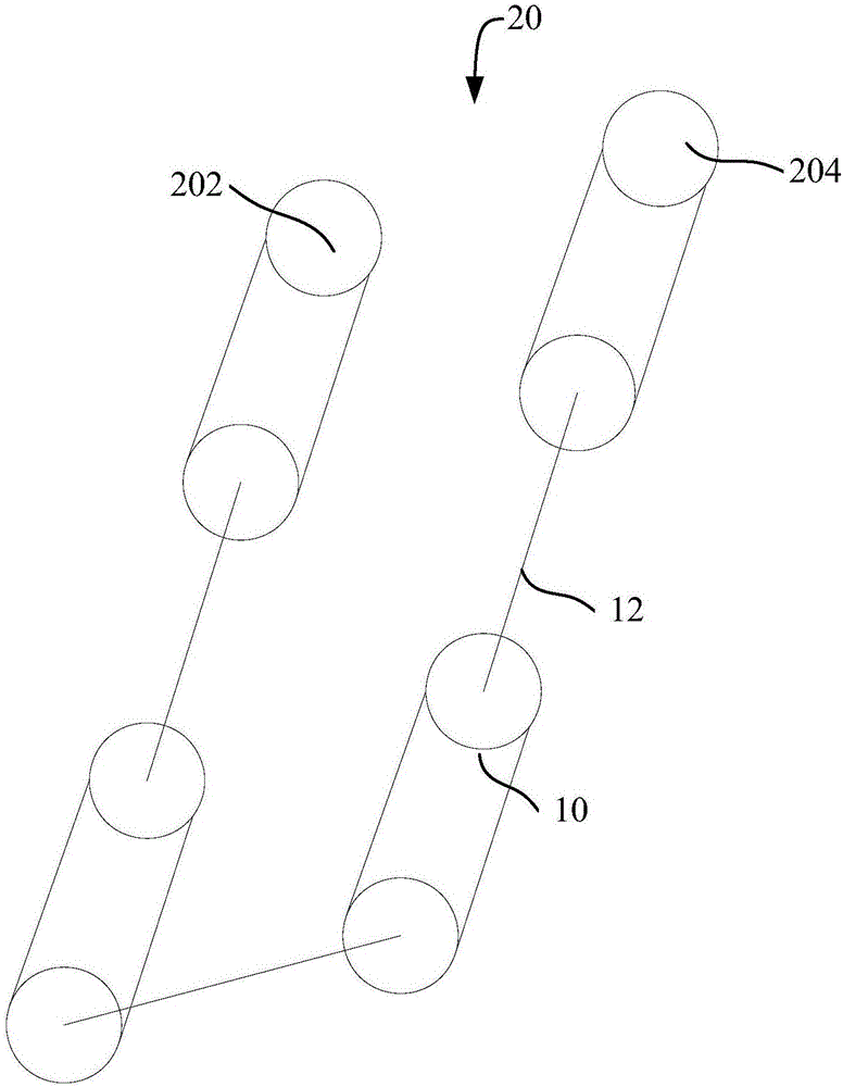
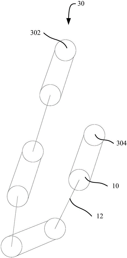
[0042] Refer below Figure 1 to Figure 6 The evaporator flow path structure 1 according to some embodiments of the present invention is described.

[0043] According to the embodiment of the first ...


PUM


Abstract

The invention provides an evaporator flow path structure, an evaporator, an air conditioner indoor unit and an air conditioner. The air conditioner comprises a wind wheel and an air inlet grille; the evaporator flow path structure comprises U tubes, semicircular connecting tubes, a fin, a first flow path, a second flow path, a third flow path and a fourth flow path, wherein the semicircular connecting tubes are used for communicating with the U tubes to form the flow paths; the fin is provided with two rows of intersected through holes, and the U tubes are penetrated in the through holes; the first flow path is provided with a first flow inlet and a first flow outlet; the second flow path is provided with a second flow inlet and a second flow outlet; the third flow path is provided with a third flow inlet and a third flow outlet; the fourth flow path is provided with a fourth flow inlet and a fourth flow outlet; the first flow path, the second flow path, the third flow path and the fourth flow path are provided with at least one U tube and at least one semicircular connecting tube respectively. The evaporator flow path structure provided by the invention realizes promotion of the performance of the air conditioner under the condition that a compact size of the air conditioner is ensured.

Description

technical field [0001] The invention relates to the field of household appliances, in particular to an evaporator flow path structure, an evaporator, an air conditioner indoor unit and an air conditioner. Background technique [0002] In the related art, the heat exchanger of the split wall-mounted room air conditioner usually adopts a two-fold, three-fold or multi-fold design. If the system configuration is optimal and the flow path design is optimal, it still cannot reach the design. When the cooling capacity target or the cooling capacity needs to be increased, the performance target of larger cooling capacity is generally achieved by expanding the structural size of the indoor unit and increasing the length of the heat exchanger, that is, increasing the area of ​​the heat exchanger and the circulating air volume of the indoor unit. Therefore, if you want to develop a product with double or higher cooling capacity, then the size of the indoor unit needs to be adjusted, wh...

Claims


Application Information

Patent Timeline
Patent Type & Authority Applications(China)
IPC IPC(8): F25B39/02F24F13/30F24F1/00
CPCF24F1/0059F24F13/30F25B39/028F25B2339/02
Inventor 蔡国健
Owner WUHAN REFRIGERATION EQUIP OF MIDEA GROUP
Learn More