
Cold storage combined refrigeration control method, device and cold storage engineering system

A technology of combined refrigeration and control methods, which is applied in the direction of household refrigeration devices, coolers, and cold storage rooms, can solve the problems of not involving the specific control method of ambient temperature, the inability to meet precise control requirements, and the lack of linkage between warehouses and warehouses. The refrigeration and cooling process is stable and rapid, which is beneficial to the overall management and deployment, and avoids the effect of excessive pressure drop

Active Publication Date: 2019-05-17
GREE ELECTRIC APPLIANCES INC
View PDF1 Cites 0 Cited by
  • Summary
  • Abstract
  • Description
  • Claims
  • Application Information

AI Technical Summary

Problems solved by technology

However, this temperature control method lacks the linkage between warehouses and warehouses, and cannot meet more precise control requirements, which is not conducive to the overall management and deployment of cold storage, as well as energy-saving control.
[0003] The utility model patent with the application number 201320526077.3 discloses a self-organized indoor environment intelligent control system. A non-central network of the indoor environment intelligent control system is established. The control data is generated by the non-central network and the user through the human-computer interaction control interface. Indoor sensors, electromechanical equipment and their integrated actuators (air conditioning equipment, lights, sunshades, doors and windows) are controlled, but this patent only provides a network communication method and communication architecture for building an environmental intelligent control system, and does not involve it. Specific control methods for ambient temperature

Method used


Image

  • Cold storage combined refrigeration control method, device and cold storage engineering system
  • Cold storage combined refrigeration control method, device and cold storage engineering system
  • Cold storage combined refrigeration control method, device and cold storage engineering system

Examples


Embodiment approach

[0051] According to an implementation manner of the combined refrigeration control device for the refrigerator of the present invention, n=2.

[0052] Another aspect of the present invention also provides a cold storage engineering system, which has the combined refrigeration control device for cold storage described in any one of the above items.

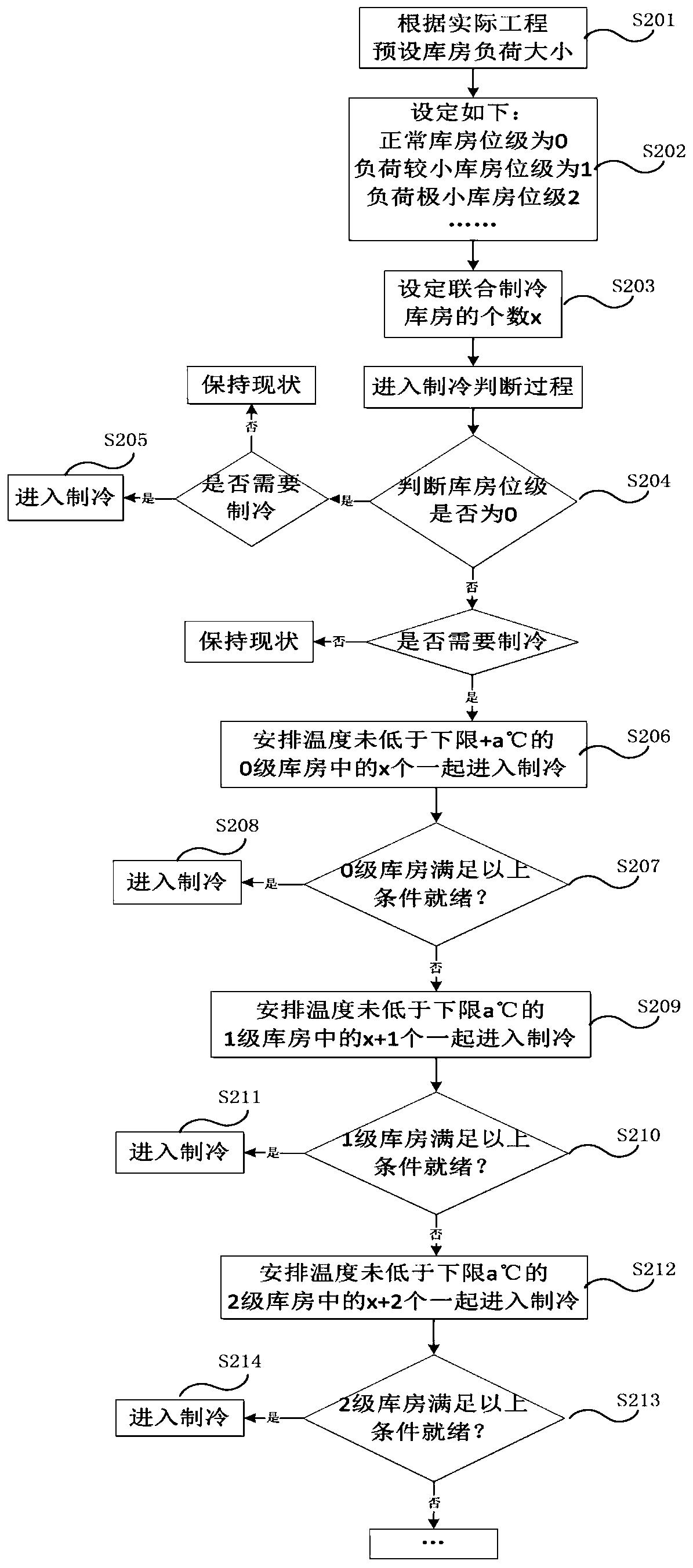
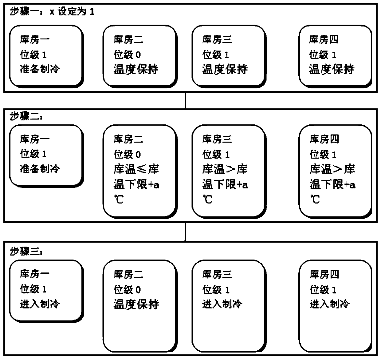
[0053] The technical solution provided by the invention integrates and concentrates the refrigeration loads of all warehouses to cool down together through the linkage between warehouses, avoiding too frequent load adjustment of the refrigeration host, and avoiding long-term operation at low-load operation with low energy efficiency; to a large extent In order to avoid the phenomenon of excessive pressure drop, frequent start-up of the refrigeration main engine, discontinuous cooling process, and long cooling time, it can ensure that the warehouse with a small cooling load can carry out the normal and continuous cooling process; the t...


PUM


Abstract

The invention provides a freezer combined refrigeration control method and device as well as a freezer engineering system. The method comprises the steps as follows: grades of freezer storerooms are divided according to refrigeration loads of the freezer storerooms; the grades include the normal grade, and if the condition that the evaporation pressure decreases rapidly cannot occur when the freezer storerooms are driven by the minimum load of a freezer unit for cooling, the freezer storerooms are divided to be the normal grade; and when the freezer storerooms with the refrigeration load smaller than the normal grade are required to start refrigeration, other freezer storerooms are organized and allocated for combined refrigeration. With the technical scheme, a refrigeration host is prevented from adjusting the load too frequently and is prevented from operating at the low load with the relatively low energy efficiency for a long term; the phenomena of too fast pressure decrease, discontinuous cooling process and long cooling time are avoided to a great extent; and overall management and allocation of freezers and energy-saving control are facilitated.

Description

technical field [0001] The invention relates to the technical field of refrigeration, in particular to a cold storage combined refrigeration control method, device and cold storage engineering system. Background technique [0002] In the cold storage engineering system, it is necessary to accurately control the temperature of the cold storage warehouse, and the temperature of the cooling process parameters is required to be stable and rapid. In the current practice, whether all warehouses in the cold storage project use a controller for centralized control similar to group control, or each warehouse in the cold storage project uses a cold storage environment controller for distributed control. Generally, only the signal collected by each warehouse temperature sensor is received, and then fed back to the corresponding warehouse electromechanical equipment through a logic algorithm, so that the actual temperature is close to the target temperature. However, this temperature c...

Claims


Application Information

Patent Timeline
Patent Type & Authority Patents(China)
IPC IPC(8): F25D29/00F25D13/04
CPCF25D13/04F25D29/00
Inventor 练浩民安亚洲何汝龙周巍
Owner GREE ELECTRIC APPLIANCES INC
Learn More