Electronic equipment foot pad detector

A technology for electronic equipment and detectors, applied in the field of electronic equipment foot pad detectors, can solve the problems of low detection efficiency and long detection time, and achieve the effect of improving detection accuracy

Pending Publication Date: 2017-06-13
SUZHOU PTC OPTICAL INSTR
View PDF15 Cites 2 Cited by
  • Summary
  • Abstract
  • Description
  • Claims
  • Application Information

AI Technical Summary

Problems solved by technology

Although this detection method will not cause scratches on the surface of the equipment to be inspected, it still needs to measure and calculate the height of the foot pads one by one, the detection time is long, and the detection efficiency is low

Method used


Image

  • Electronic equipment foot pad detector
  • Electronic equipment foot pad detector
  • Electronic equipment foot pad detector

Examples


Embodiment Construction

[0027] The following description serves to disclose the present invention to enable those skilled in the art to carry out the present invention. The preferred embodiments described below are only examples, and those skilled in the art can devise other obvious variations. The basic principles of the present invention defined in the following description can be applied to other embodiments, variations, improvements, equivalents and other technical solutions without departing from the spirit and scope of the present invention.

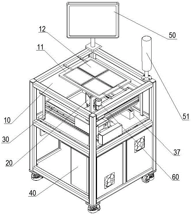
[0028] figure 1 It shows a schematic structural diagram of an embodiment of the electronic equipment foot pad detector of the present invention, which is also a schematic diagram of a preferred embodiment. Such as figure 1 The shown electronic equipment floor pad detector includes a detection workbench 10 for placing the equipment to be inspected. The detection workbench 10 is provided with a detection area 11 made of a transparent material. The detecti...


PUM


Abstract

The invention belongs to the field of automatic detection, and particularly relates to an electronic equipment foot pad detector capable of detecting the coplanarity of foot pads. The electronic equipment foot pad detector comprises a detection working table for placing equipment to be detected, and a detection region which is arranged on the detection working table and is made of a transparent material, wherein a touch screen is arranged on the upper side of the detection region; the touch screen is used for receiving pressure information of the foot pads of the equipment to be detected, acquiring coordinate information of the foot pads according to the received pressure information, and transmitting the acquired coordinate information to a control mechanism; a distance measurer for measuring a vertical distance between the foot pads of the equipment to be detected and the detection region and a displacement mechanism for driving the distance measurer to move below the detection region are arranged below the detection region; the control mechanism electrically connected with the touch screen, the distance measurer and the displacement mechanism is arranged below the displacement mechanism. The detector disclosed by the invention has the advantages of short detection time and high detection efficiency, no manual measurement, high detection precision, time saving, labor saving and wide market prospect.

Description

technical field [0001] The invention belongs to the field of automatic detection, and in particular relates to a foot pad detector for electronic equipment capable of detecting the coplanarity of the foot pads. Background technique [0002] With the rapid development of Internet technology, various electronic devices and their peripheral devices emerge in endlessly in people's lives. Such as laptops, computer keyboards, computer mice, etc., in order to enhance the stability and performance of the equipment, the bottom of these electronic devices is usually provided with foot pads, although the foot pads are an extremely small part in the entire electronic device, but these Parts that appear to be insignificant on the surface play a key role in the good performance of electronic equipment, especially for laptops, the importance of foot pads cannot be underestimated. In addition to the well-known anti-slip, which can make the notebook computer stand on the desktop stably, the...

Claims


Application Information

Patent Timeline
Patent Type & Authority Applications(China)
IPC IPC(8): G01B21/30
CPCG01B21/30
Inventor 唐翔闫飞龙怀玉朱信良杨晓宁袁绪伟
Owner SUZHOU PTC OPTICAL INSTR
Why Eureka
Try Eureka