
Solid expandable tubular loaded bending expansion test device

A technology of expansion test and bending test, which is applied in the direction of testing material strength by applying stable bending force and testing material strength by applying stable tension/pressure, which can solve the hidden dangers of safety and reliability of the expanded pipe body and the inability to expand the full size of the pipe Evaluation test and other issues, to achieve the effect of simple and reliable device structure

Active Publication Date: 2017-06-13
中国石油集团石油管工程技术研究院 +1
View PDF6 Cites 0 Cited by
  • Summary
  • Abstract
  • Description
  • Claims
  • Application Information

AI Technical Summary

Problems solved by technology

The expansion tube products developed in China are only based on the requirements of the expansion process. After the tube body and the expansion tool are assembled, the relevant physical performance tests such as internal pressure and sealing are carried out on the ground, and there is no device for the expansion performance test of the physical expansion tube. , the previous domestic patents ZL201010285911.5, ZL201010507489.3, etc. can only complete the expansion experiment evaluation of straight expansion pipes. As for the expansion pipe, it is currently used in the downhole due to the twists and turns of the well wall or the large arc of the horizontal well. Most of the sections are in a bent state, and the current evaluation test equipment and means cannot conduct full-scale evaluation tests on the expansion pipe under this working condition, resulting in hidden dangers to the safety and reliability of the expansion pipe during underground service. This is also an important gap between domestic expansion tube technology and similar foreign technologies

Method used


Image

  • Solid expandable tubular loaded bending expansion test device
  • Solid expandable tubular loaded bending expansion test device
  • Solid expandable tubular loaded bending expansion test device

Examples


Embodiment Construction

[0023] The present invention will be described in detail below in conjunction with the accompanying drawings and embodiments.

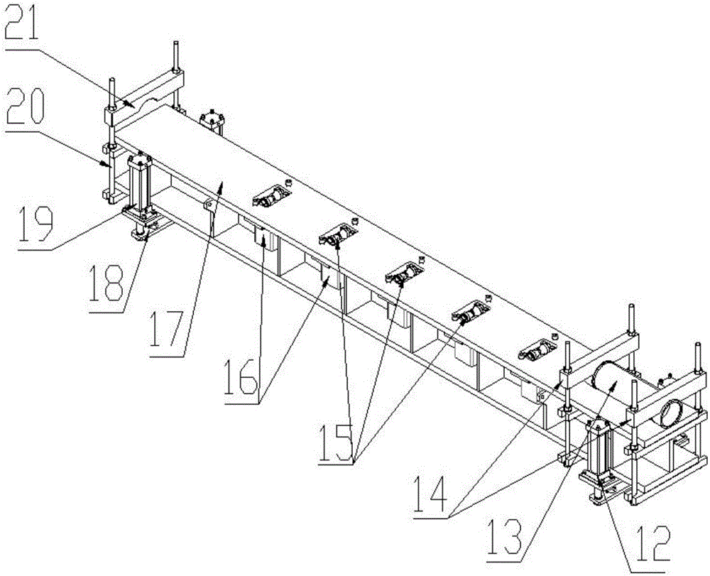
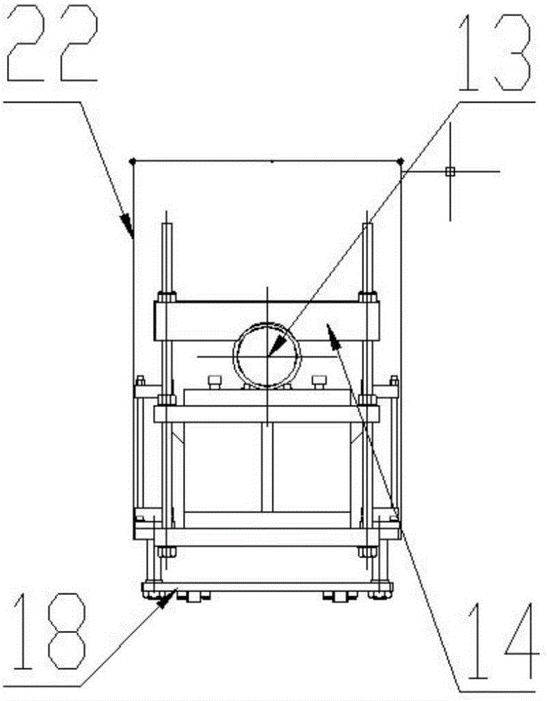
[0024] The solid expansion pipe load bending expansion test device provided in the embodiment is composed of a loading frame and a bending test platform.

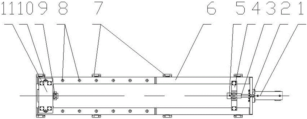
[0025] Such as figure 1 As shown, the loading frame adopts a horizontal structure, which is composed of a hydraulic cylinder 1, a main frame 6 and a frame bracket 7. The main frame 6 adopts a welded steel structure and is rectangular in design. The bending test platform, the frame material has been annealed and can meet the maximum load of 2000KN. On the right side of the main frame 6, the piston rod 3 is connected to the hydraulic cylinder 1, and the piston rod 3 is connected to the tension chuck 5, which is used to connect the expansion tube for the test and apply axial load. The chuck fixing frame 4 is connected to the main frame 6 Linked to support the tension chuck 5. A reaction force frame...


PUM


Abstract

The invention relates to the field of solid expandable tubes in petroleum and natural gas industries and in particular relates to a solid expandable tubular loaded bending expansion test device. The device is used for overcoming the defects in the prior art that an expansion tube in a bending state cannot be subjected to a full-scale evaluation test and hidden danger of safety and reliability of the expansion tube in the downhole service process is caused. The device comprises a loading frame and a bending test platform arranged in the loading frame, wherein the loading frame comprises a main frame; a hydraulic cylinder is arranged on one side of the main frame and connected with one end of a piston rod; the other end of the piston rod is connected with a tensile chuck; a reactive force frame capable of moving in the axial direction is arranged on the other side of the main frame; a permanent joint is arranged on the reactive force frame; multiple v-shaped rollers are distributed on the bending test platform in equal distance; the hydraulic cylinder is connected below each of the v-shaped rollers; a floating sleeve is arranged at one end of the bending test platform; a fixed pressing plate is arranged at the other end of the bending test platform; and a connecting bracket is arranged on the lower part of the bending test platform.

Description

technical field [0001] The invention relates to the technical field of solid expansion pipes in the petroleum and natural gas industry, in particular to a load-bearing bending expansion test device for solid expansion pipes. Background technique [0002] Solid Expandable Tubular SET (Solid Expandable Tubular) technology is a new drilling, completion and workover technology that radially expands the casing string to the required diameter in the wellbore for the purpose of "saving" the borehole size . The application of this technology can increase the number of casing layers to be lowered, bringing "revolutionary" impact and significant technical and economic benefits to deep wells, drilling and wellbore structures with complex geological conditions. It can make the wellbore "thin" and significantly reduce the development cost. It makes "single diameter" possible. [0003] The solid expansion tube technology has been developed and applied very rapidly all over the world. T...

Claims


Application Information

Patent Timeline
IPC IPC(8): G01N3/20G01N3/12
Inventor 刘强宋生印白强汪蓬勃贾鹏军
Owner 中国石油集团石油管工程技术研究院
Features
  • Generate Ideas
  • Intellectual Property
  • Life Sciences
  • Materials
  • Tech Scout
  • Unparalleled Data Quality
  • Higher Quality Content
  • 60% Fewer Hallucinations
Learn More