Induced eddy current thermal imaging detection device on basis of rotary magnetic fields

A rotating magnetic field and imaging detection technology, which is applied in the field of induction eddy current thermal imaging detection devices, can solve problems such as low efficiency and uneven heating, and achieve the effect of simplifying the heating system and solving uneven heating

Inactive Publication Date: 2017-06-13
SICHUAN UNIV
View PDF6 Cites 6 Cited by
  • Summary
  • Abstract
  • Description
  • Claims
  • Application Information

AI Technical Summary

Problems solved by technology

[0004] In view of the current situation and shortcomings of conventional eddy current thermal imaging detection technology, the purpose of the present invention is to provide an induction eddy current thermal imaging detection device based on a rotating magnetic field to solve the problems of uneven heating and low efficiency in conventional eddy current thermal imaging detection technology

Method used


Image

  • Induced eddy current thermal imaging detection device on basis of rotary magnetic fields
  • Induced eddy current thermal imaging detection device on basis of rotary magnetic fields
  • Induced eddy current thermal imaging detection device on basis of rotary magnetic fields

Examples


Embodiment Construction

[0022] The specific embodiments of the present invention will be given below in conjunction with the accompanying drawings, and the rotating magnetic field-based induction eddy current thermal imaging detection device of the present invention will be further described through the specific embodiments. It should be pointed out that the specific implementation of the present invention is not limited to the forms described in the examples.

[0023] The directional terms mentioned in the detailed description below, such as: up, down, left, right, front, back, etc., are only directions referring to the drawings. Therefore, the directional terms used are only for the convenience of explaining the present invention, and are not intended to limit the present invention.

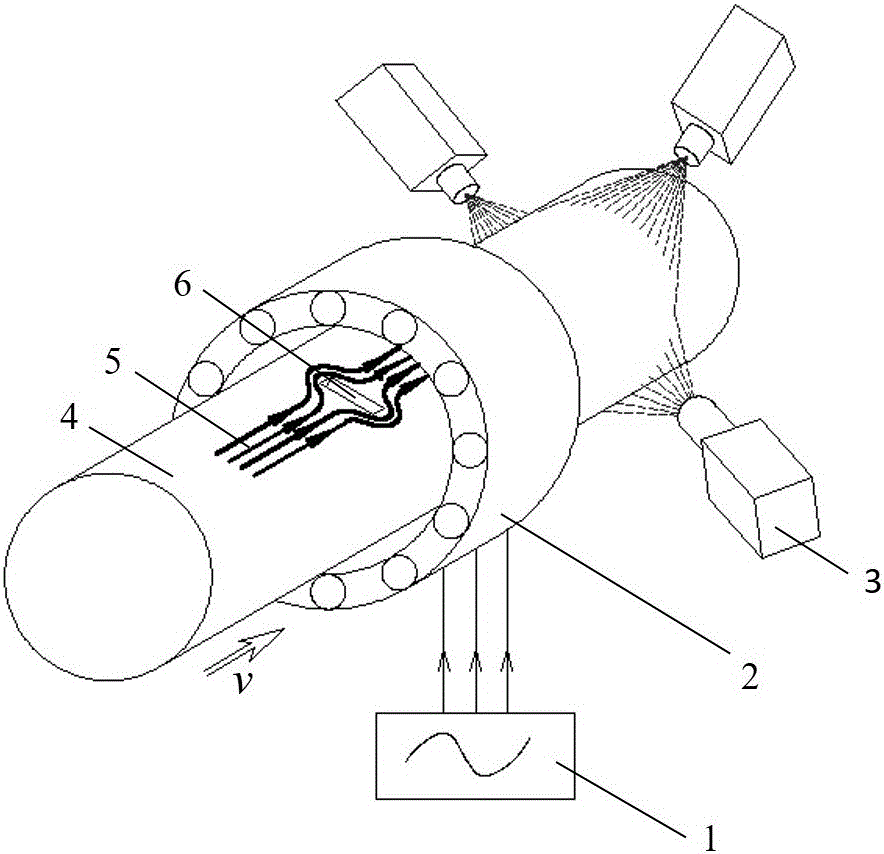
[0024] The structure diagram of the inductive eddy current thermal imaging detection device based on the rotating magnetic field in this embodiment is as follows figure 1 As shown, the composition includes: a rotatin...


PUM


Abstract

The invention discloses an induced eddy current thermal imaging detection device on the basis of rotary magnetic fields. The induced eddy current thermal imaging detection device comprises a rotary magnetic field excitation power source, a rotary magnetic field generator and an infrared thermal imager. Multi-phase asynchronous alternating currents can be provided for the rotary magnetic field generator by the rotary magnetic field excitation power source, and the rotary magnetic fields can be generated inside the rotary magnetic field generator. A detected test piece arranged inside the rotary magnetic field generator can move relative to the rotary magnetic fields, induction electromotive force can be generated by cut magnetic induction lines on the basis of the Faraday law of electromagnetic induction, and motional eddy current can be generated. Propagation of the motional eddy current can be obstructed when defects are available in the test piece, accordingly, the density of eddy current on the periphery of crack can be obviously increased, the temperature of the periphery of the crack is obviously higher than the temperatures of regions without the defects according to the Joule law, distribution of the surface temperatures of the detected test piece can be picked up by the infrared thermal imager positioned at the tail end of the induced eddy current thermal imaging detection device, and accordingly the availability of the defects can be detected. The induced eddy current thermal imaging detection device has the advantages that the test piece can be uniformly heated by the induced eddy current thermal imaging detection device in all circumferential directions, accordingly, the detection efficiency can be improved, and the cost can be reduced.

Description

technical field [0001] The invention relates to the field of eddy current thermal imaging non-destructive testing, in particular to an induction eddy current thermal imaging detection device based on a rotating magnetic field. Background technique [0002] As a non-contact non-destructive testing method, eddy current thermal imaging is now widely used in controlling product quality and ensuring the safe operation of in-service equipment. It combines eddy current with thermal imaging technology, which can realize the rapid detection of defects in a wide range of different depths. In recent years, it has been widely used in the field of non-destructive testing of conductor materials, and has become an important basis for analyzing the cause of conductor material failure. [0003] At present, the conventional eddy current thermal testing method is to pass a single high-frequency alternating current into a single wire or a single coil, and through electromagnetic induction, an i...

Claims


Application Information

Patent Timeline
IPC IPC(8): G01N25/72
CPCG01N25/72
Inventor 伍剑波黄晓明王杰
Owner SICHUAN UNIV
Why Eureka
Try Eureka