Optical fiber clamping tool for optical fiber fusion splicer

A technology of optical fiber fusion splicer and optical fiber clamp, which is applied in the direction of optics, light guides, optical components, etc., can solve the problems of high cost and inability to solve the problem of ribbon optical fiber clamping, and achieve the goal of reducing fusion loss, improving fusion efficiency and reducing costs Effect

Pending Publication Date: 2017-06-13
INNO INSTR (CHINA) INC
View PDF13 Cites 7 Cited by
  • Summary
  • Abstract
  • Description
  • Claims
  • Application Information

AI Technical Summary

Problems solved by technology

[0004] But this kind of fixture can't solve the clamping problem of 200μm (including coating) ribbon fiber, and using this fixture can't make the new ribbon fiber use the original fiber fusion splicer for fusion splicing, and in the field of engineering operations, buying new Fiber splicers are often cost-prohibitive

Method used


Image

  • Optical fiber clamping tool for optical fiber fusion splicer
  • Optical fiber clamping tool for optical fiber fusion splicer
  • Optical fiber clamping tool for optical fiber fusion splicer

Examples


Embodiment Construction

[0028] Hereinafter, the present invention will be further described based on preferred embodiments with reference to the accompanying drawings.

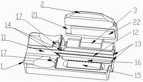
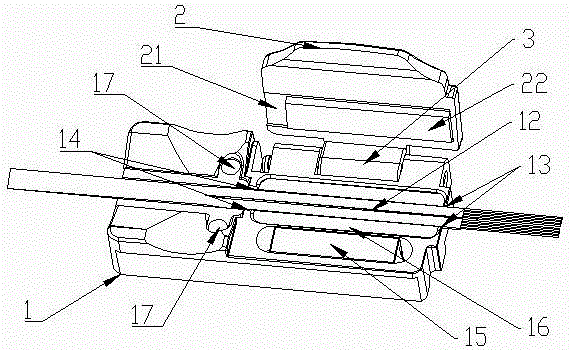
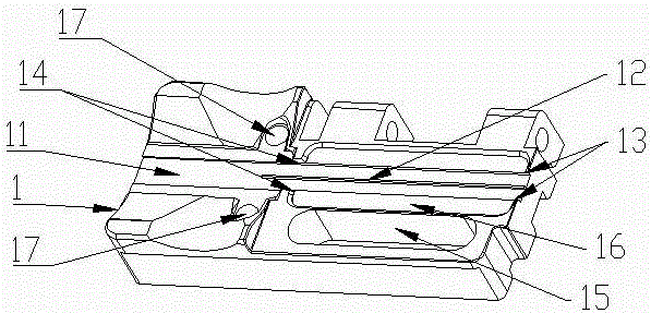
[0029] refer to figure 1 , the present invention discloses an optical fiber clamping tool for an optical fiber fusion splicer, comprising a body 1 and a cover 2 , the body 1 and the cover 2 are pivotally connected through a rotating shaft 3 .

[0030] The main body 1 is provided with an optical fiber placement groove 11 for placing a 12-core ribbon optical fiber with a diameter of 200 μm, and the optical fiber placement groove 11 runs through the main body 1 in the length direction; its width is set at 2.80mm~2.84mm between mm.

[0031] refer to figure 2 , the optical fiber placement groove 11 is provided with a raised strip 12, the raised strip 12 is set as a cuboid protruding from the optical fiber placement groove 11, the raised strip 12 is parallel to the two long sides of the optical fiber placement groove 11, and Divide the...


PUM


Abstract

The invention discloses an optical fiber clamping tool for an optical fiber fusion splicer. The optical fiber clamping tool comprises a body and a cover body, wherein the body is pivotally connected with the cover body through a rotating shaft, an optical fiber placement groove, optical fiber confinement front parts and optical fiber confinement rear parts are arranged on the body, a rib is arranged in the optical fiber placement groove, an optical fiber fixing part for fixing an optical fiber is arranged on the cover body, and an elastic body is arranged in the optical fiber fixing part. According to the optical fiber clamping tool, a 12-core ribbon optical fiber with a diameter of 200mu m can be accommodated and clamped; in addition, the original optical fiber fusion splicer can be used for a new optical fiber, so that the fusion splicing quality is ensured, and meanwhile, the cost is reduced.

Description

technical field [0001] The invention relates to the field of optical fiber clamps, in particular to a multi-purpose optical fiber clamping tool suitable for optical fiber cutters and optical fiber fusion splicers. Background technique [0002] Optical fiber, short for optical fiber, is a fiber made of glass or plastic that can be used as a light transmission tool. The ribbon optical fiber is to stick multi-core optical fibers (4, 6, 8, 12 cores, etc.) , the most commonly used ribbon fiber with 6 cores and 12 cores. The ribbon optical fiber that appeared before is mainly composed of ribbon optical fiber with a diameter of 250 μm (including coating). With the development of optical fiber technology, ribbon optical fiber with a diameter of 200 μm (including coating) has appeared recently. The new ribbon optical fiber The emergence of optical fibers makes the original optical fiber clamping tools unusable, and at the same time, the new ribbon optical fiber cannot be placed on ...

Claims


Application Information

Patent Timeline
Patent Type & Authority Applications(China)
IPC IPC(8): G02B6/255
CPCG02B6/255G02B6/2556G02B6/25G02B6/3616G02B6/2553G02B6/3858G02B6/0021G02B6/2551
Inventor 赵阳日
Owner INNO INSTR (CHINA) INC
Why Eureka
Try Eureka