Supercharge Your Innovation With Domain-Expert AI Agents!

Design method of shield machine box culvert crane beam structure based on ansys node coupling

A beam structure and box culvert technology, applied in design optimization/simulation, calculation, mining equipment, etc.

Inactive Publication Date: 2019-02-01
辽宁三三工业有限公司
View PDF2 Cites 0 Cited by
  • Summary
  • Abstract
  • Description
  • Claims
  • Application Information

AI Technical Summary

Problems solved by technology

In the previous design, only the truss girder was calculated without considering the track girder, or the structural calculation or simulation method that modeled the crane truss girder and the track girder as an integral model had shortcomings

Method used


Image

  • Design method of shield machine box culvert crane beam structure based on ansys node coupling
  • Design method of shield machine box culvert crane beam structure based on ansys node coupling
  • Design method of shield machine box culvert crane beam structure based on ansys node coupling

Examples


Embodiment Construction

[0019] The technical solutions of the present invention will be further specifically described below through the embodiments and in conjunction with the accompanying drawings.

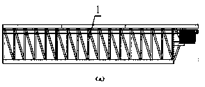
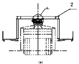
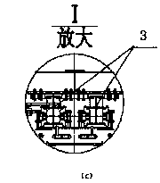
[0020] As shown in Figure 1, the box culvert crane beam 1 is composed of a truss beam 2 and a track beam 3, which are connected together by bolts and pressure plates, and the box culvert crane moves on the track beam 3 when it is working;

[0021] The invention provides a method for designing a shield machine box culvert crane beam structure based on ANSYS node coupling, comprising the following steps:

[0022] (1) Use the beam element BEAM188 in the finite element software ANSYS to establish a geometric model for the box culvert crane beam, and assign each beam with its own section parameters and materials;

[0023] (2) After the geometric model is established, the geometric model is discretized into a finite element model through the mesh division function of ANSYS, such as figure 2 As shown, when t...


PUM


Abstract

The invention relates to a shield-machine-road-element-crane-beam structure design method based on ANSYS node coupling. A road-element-crane beam is composed of a truss beam and rail beams, and the truss beam is connected with the rail beams through bolts and pressing plates; a road element crane suspends, loads and moves on the rail beams when working, the structural relationship connected through the bolts and the pressing plates between the truss beam an the rail beams is simulated through ANSYS node coupling, the stress condition of the crane rail beams is well simulated, the accurate crane-beam strength and rigidity results can be obtained through calculation, and reliable data is provided for designing the crane beam and a rail.

Description

technical field [0001] The invention relates to a design of underground shield construction equipment, in particular to a design method of a shield machine box culvert crane beam structure based on ANSYS software. Background technique [0002] The box culvert crane beam is composed of the truss crane beam and the crane track beam, which are used to travel the box culvert crane and the segment crane; the truss crane beam and the crane track beam simultaneously bear the load of the crane when the crane is working The track beam of the truss crane is fixed on the lower part of the truss crane beam by a number of pressure plates through bolts. When transporting box culverts or segments, the crane walks on the track beam and transmits the load to the truss crane beam through the pressure plates and bolts. Therefore, when the crane is working The displacement (deformation) of the truss crane beam and the track beam is the same, and the truss crane beam and the track beam distribut...

Claims


Application Information

Patent Timeline
Patent Type & Authority Patents(China)
IPC IPC(8): G06F17/50E21D9/06
CPCE21D9/06G06F30/17G06F30/23
Inventor 于学鹏刘双仲孟宪超
Owner 辽宁三三工业有限公司
Features
  • R&D
  • Intellectual Property
  • Life Sciences
  • Materials
  • Tech Scout
  • Unparalleled Data Quality
  • Higher Quality Content
  • 60% Fewer Hallucinations
Learn More