
A laboratory test device for simulating the flow field of salt rock karst cavity construction

A laboratory simulation, salt rock karst cavity technology, applied in the direction of measuring devices, material analysis through optical means, instruments, etc., can solve the problem of slow construction speed, insufficient, and difficult dissolution of the salt body on the inner wall of the karst cavity. Grasp and other issues to achieve the effect of strong reliability, small size and high efficiency

Active Publication Date: 2018-01-30
CHINA PETROLEUM & CHEM CORP +1
View PDF6 Cites 0 Cited by
  • Summary
  • Abstract
  • Description
  • Claims
  • Application Information

AI Technical Summary

Problems solved by technology

However, in the process of using the traditional water dissolution method to construct a salt rock cavern, the research on the flow field shape and concentration field distribution inside the cavern, the stress and strain of the cavern string, and the pressure change of the cavern during operation and construction are still insufficient. , it is difficult to grasp the upper and side dissolution state of the salt body on the inner wall of the karst cave, which makes it difficult to control the shape of the salt karst cavern, and it is impossible to accurately grasp the pressure relief time of the cavity before construction, which leads to the failure of the underground salt cavern gas storage. Construction delays, slow construction
Since the salt rock karst cavity is buried deep underground, it is impossible to directly observe it with the existing technical means. Therefore, by simulating the flow field shape of the salt rock karst cavity during the cavity construction period in the laboratory simulation device, the underground salt rock gas storage The design research of the library has certain guiding significance

Method used


Image

  • A laboratory test device for simulating the flow field of salt rock karst cavity construction

Examples


Embodiment Construction

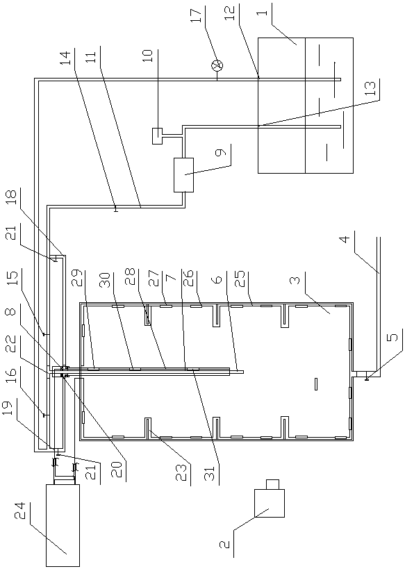
[0034] Such as figure 1 As shown, the present invention includes a water tank 1, an image recorder 2, a simulated salt karst cavity 3 made of organic glass, and a signal transmitting and receiving processor 24. The inner wall of the simulated salt karst cavity 3 is provided with a simulated interlayer device 23, and the image recorder 2 is provided On one side of the simulated salt karst cavity 3, the image recorder 2 is a digital video camera and / or camera.

[0035] The bottom of the simulated salt karst cavity 3 is provided with an outlet pipe 4, the first valve 5 is connected to the outlet pipe 4, a central pipe 6 is vertically arranged in the simulated salt karst cavity 3, and an intermediate pipe 7 is placed outside the central pipe 6. 7 is connected to the central pipe 6 through the hanger 8, and both the central pipe 6 and the intermediate pipe 7 extend upward to simulate the salt karst cavity 3.

[0036] The water tank 1 is provided with a circulating water inlet 12 and a ...


PUM


Abstract

The invention discloses a test device for simulating the flow field of salt rock cavern construction in a laboratory, which belongs to the technical field of salt rock underground gas storage cavity construction. It includes a water tank, an image recorder and a simulated salt karst cavity made of transparent material. The simulated salt karst cavity is equipped with a central pipe and an intermediate pipe; the circulating water outlet of the water tank is connected to the constant flow pump, the second valve, the third valve and the fourth valve in sequence. Afterwards, it is connected with the circulating water inlet of the water tank. There are second pipes connected between the second valve and the third valve and the outlet of the fourth valve respectively. The second pipes are all connected with the intermediate pipe. Five valves, the upper end of the central pipe is connected to the first pipe between the third valve and the fourth valve; the image recorder is set on one side of the simulated salt rock cavern. The present invention has the advantages of high efficiency and high reliability compared with the actual design of the dissolution chamber on site, and can perform similar simulation on the internal flow field form of the giant dissolution chamber thousands of meters deep underground.

Description

Technical field [0001] The invention belongs to the technical field of cavern building for salt rock underground gas storage, and is specifically a laboratory test device for simulating a salt rock cavern to build a flow field. Background technique [0002] With the rapid development of economy and society, the national energy strategic reserve is becoming increasingly urgent. Due to the excellent geological occurrence conditions, good sealing, and high degree of safety and stability, the underground salt karst cavity is recognized as an ideal place for oil and gas storage and waste disposal. The downstream supporting gas storage of my country's West-East Gas Pipeline Project is located in salt karst caves. At present, oil storage in central my country is also selected to be built in salt karst caves. However, in the process of constructing salt karst cavity by traditional water solution method, the research on the flow field shape, concentration field distribution, stress and s...

Claims


Application Information

Patent Timeline
Patent Type & Authority Patents(China)
IPC IPC(8): G01N21/84G01D21/02
Inventor 张格戴鑫唐礼骅唐海军李汉周
Owner CHINA PETROLEUM & CHEM CORP
Learn More