Calculation method of spur gear wear
A technology of spur gears and calculation methods, applied in calculation, design optimization/simulation, instruments, etc., can solve the problems of vibration shock, meshing point deviation, unable to truly reflect the dynamic load between teeth, etc., so as to prolong the service life of gears. , Reduce the effect of gear vibration and shock
Active Publication Date: 2019-10-01
NORTHEASTERN UNIV LIAONING
View PDF2 Cites 0 Cited by
- Summary
- Abstract
- Description
- Claims
- Application Information
AI Technical Summary
Problems solved by technology
The above two cases of determining the meshing load in the double-tooth meshing area cannot truly reflect the dynamic load between the teeth, because in the low-speed heavy-duty gear, the wear inevitably forms a gap between the teeth, causing the meshing point to deviate from the ideal gradient. Open wire position, causing vibration shock
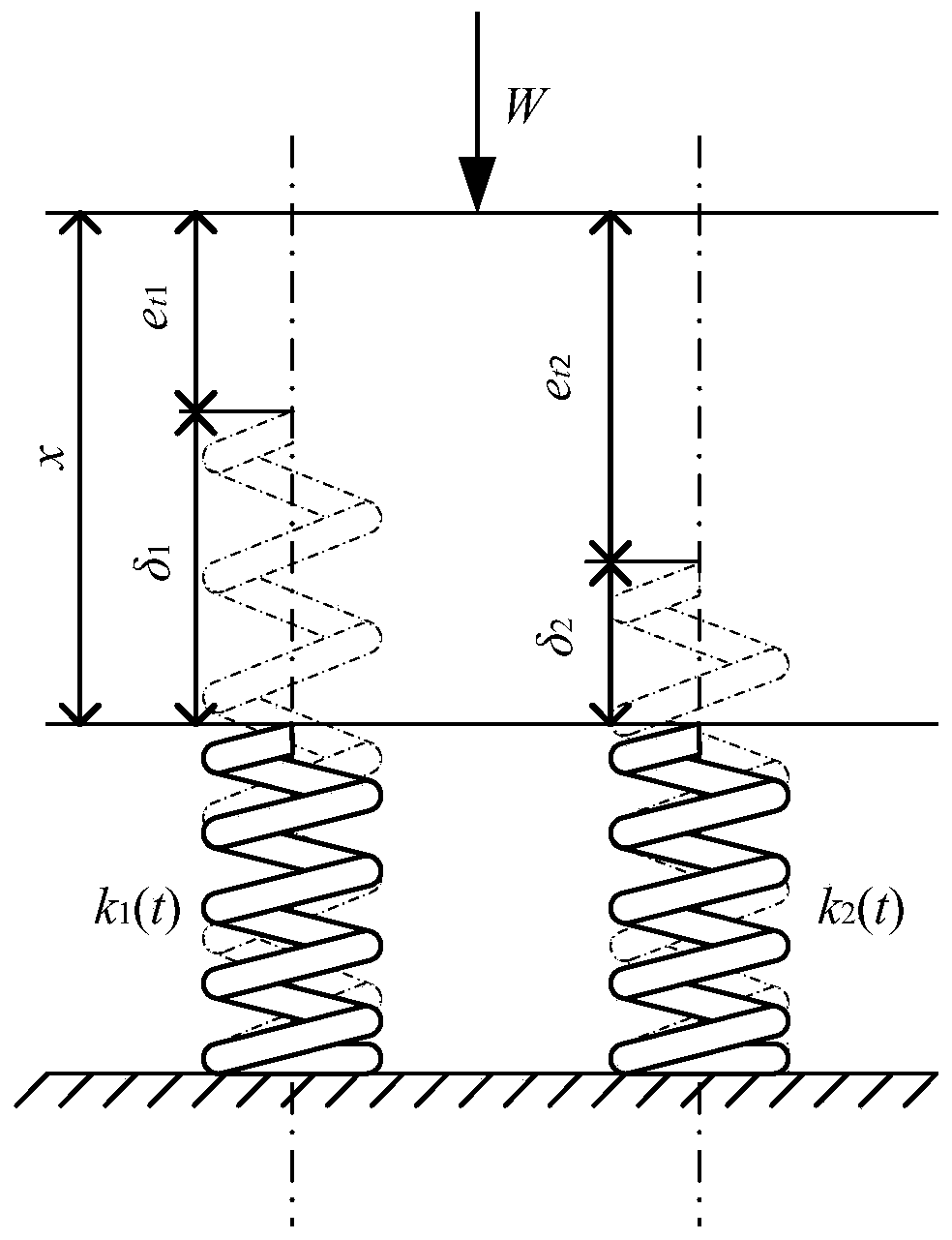
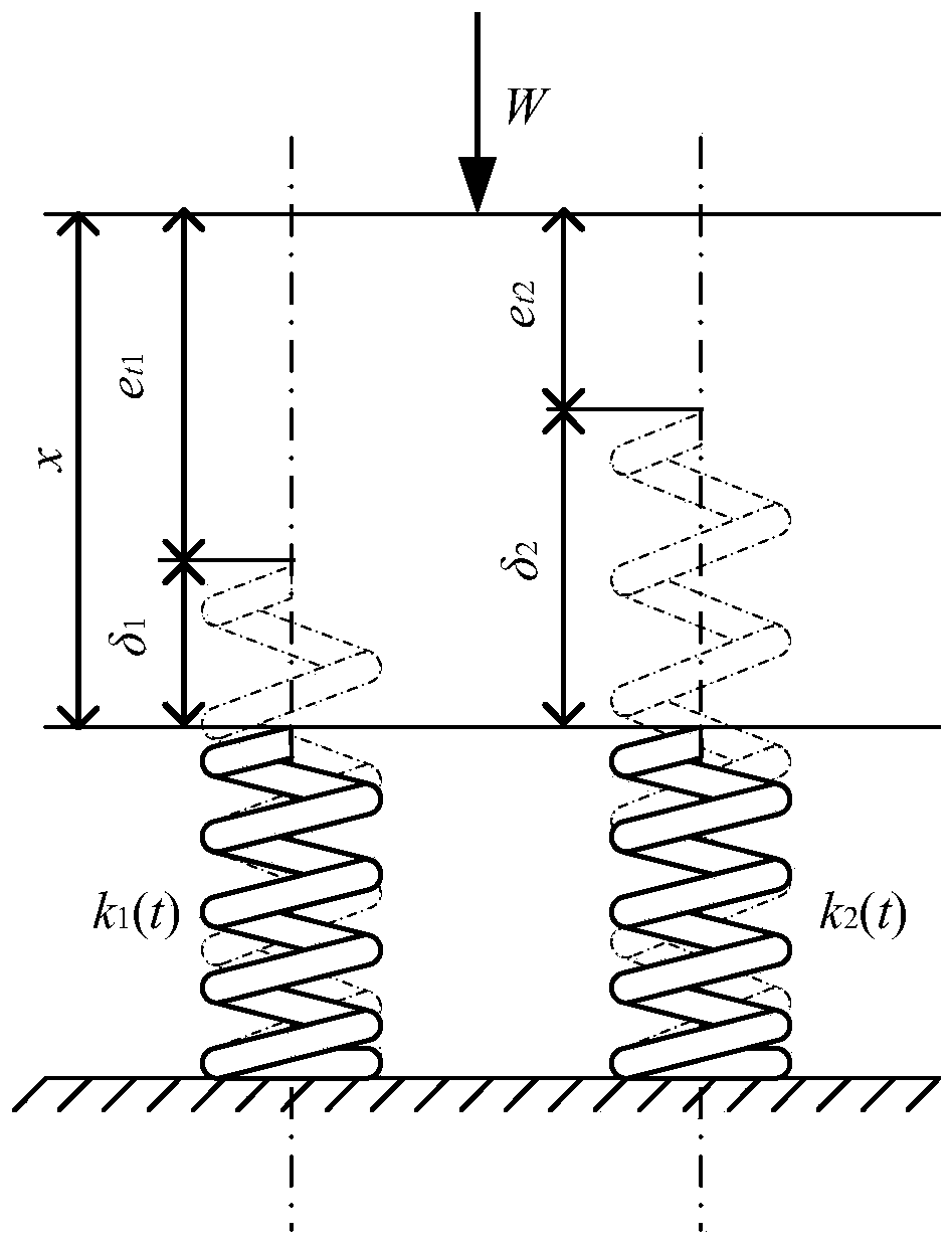
Regardless of the influence of the amount of wear on the dynamic load between the teeth, the two pairs of meshing gear meshing pairs are directly regarded as a pair of parallel springs for load distribution, and only the time-varying stiffness of each pair of tooth meshing pairs along the meshing line is considered. Truly reflect the dynamic load between teeth
Method used
View moreImage
Smart ImageViewing Examples
Examples
Embodiment Construction
Login to View More PUM
 Abstract
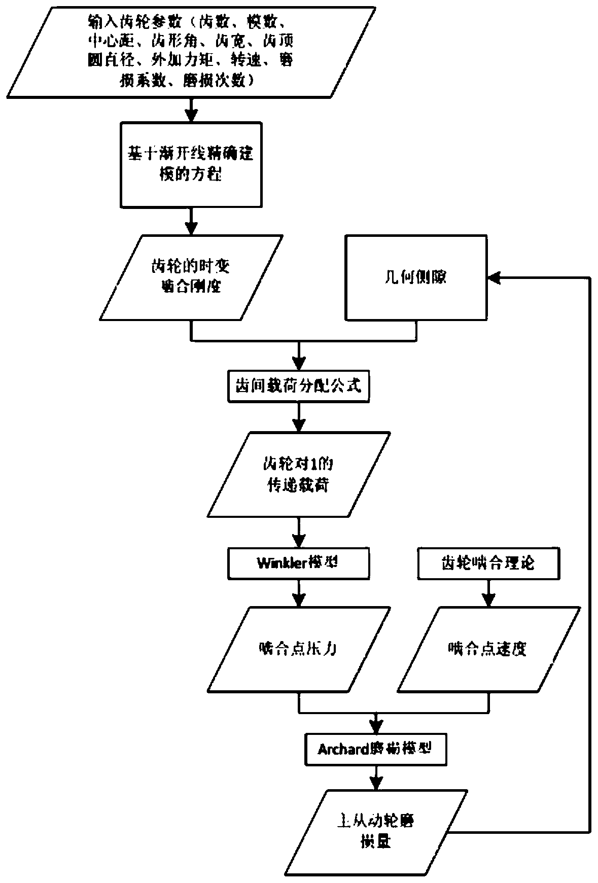
The invention relates to a method for calculating the wear amount of spur gear cylindrical gears. The calculation method of spur gear wear amount includes the following specific process: Step 1: According to the time-varying meshing stiffness of the gear and the geometric backlash of the gear, determine the inter-tooth dynamic load borne by the two pairs of gear tooth meshing pairs, and calculate the meshing point The surface pressure of Calculate the wear depth calculated in step 3. The calculation method of spur gear wear amount takes into account the dynamic load update process under actual geometric backlash, accurately and reasonably determines the wear amount of spur gear teeth at each position, and provides an effective way to reduce gear vibration impact and extend gear service life. .
Description
technical field The invention relates to a method for calculating the wear amount of spur gears. Background technique In the process of transmission of power, gears inevitably suffer from friction and wear. Although the wear is slightly harmless during the initial running-in process, as the wear continues to accumulate, the changes in the gear tooth profile shape and size parameters will This leads to the deterioration of the contact environment, resulting in a greater dynamic load between the teeth, resulting in a more serious form of gear tooth failure, which in turn increases the vibration and impact of the gear and reduces the service life of the gear. At present, the numerical calculation technology of gear wear is generally based on the Archard wear model, which involves the determination of the meshing load of the gear and the sliding distance of the tooth surface. In a gear meshing cycle, double-tooth meshing and single-tooth meshing appear alternately. In the sin...
Claims
Login to View More Application Information
Patent Timeline
 Patent Type & Authority Patents(China)
IPC IPC(8): G06F17/50
CPCG06F30/20
Inventor 朱丽莎向磊
Owner NORTHEASTERN UNIV LIAONING
Features
- R&D
- Intellectual Property
- Life Sciences
- Materials
- Tech Scout
- Unparalleled Data Quality
- Higher Quality Content
- 60% Fewer Hallucinations
Learn More Browse by: Latest US Patents, China's latest patents, Technical Efficacy Thesaurus, Application Domain, Technology Topic, Popular Technical Reports.
© 2025 PatSnap. All rights reserved.Legal|Privacy policy|Modern Slavery Act Transparency Statement|Sitemap|About US| Contact US: help@patsnap.com


