Reel holder for high speed elastic wire winder

An elastic wire and coiler technology, applied in the direction of conveying filamentous materials, thin material handling, transportation and packaging, etc., can solve the problems of short life of O-rings, weak gripping force, and weak rotation characteristics of spool clamps. , to achieve the effect of prolonging the service life and increasing the gripping force

Inactive Publication Date: 2004-02-04
ILJIN A TECH
View PDF0 Cites 4 Cited by
  • Summary
  • Abstract
  • Description
  • Claims
  • Application Information

AI Technical Summary

Problems solved by technology

[0008] First, the support structure of the shaft and the cylinder connecting the shaft is very weak because the support point of the cylinder and the shaft is formed only in a single area
[0009] Second, the O-ring with a small surface area is pushed outward or returned to the original position by means of the clamping member, and the bobbin is grasped or released. The lifespan is also short, and the grip is weak, too
[0010] Third, because the shaft and the cylinder are connected together in a straight line, there is a lack of solidity as a whole. Therefore, the natural vibration number of the bobbin holder, that is, the resonance frequency will become smaller. As a result, the critical rotational speed of the bobbin holder and the speed at which the elastic yarn is taken up will slow down
[0011] Fourth, the spool holder is coupled to the motor in the form of 2 links through a coupling, so the amount of vibration impact reduction due to misalignment is reduced, so the rotation characteristics of the spool holder will be weakened

Method used


Image

  • Reel holder for high speed elastic wire winder
  • Reel holder for high speed elastic wire winder
  • Reel holder for high speed elastic wire winder

Examples


Embodiment Construction

[0038] Hereinafter, the present invention will be described in detail with reference to the drawings.

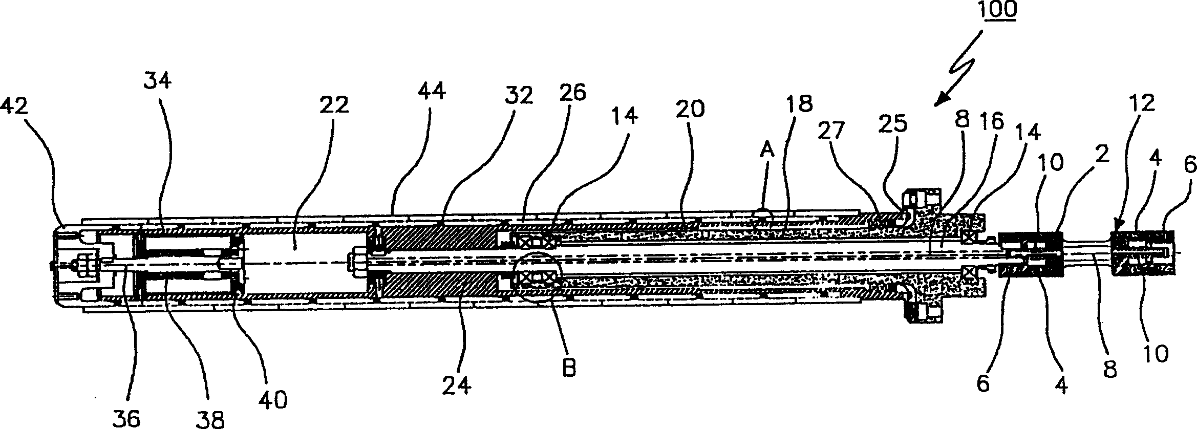
[0039] figure 2 A sectional view showing a bobbin gripper 100 of a coiler for high-speed elastic yarn coiling.

[0040] As shown in the figure, the spool gripper 100 of the present invention has a shaft coupling 12, the first body 2, the star wheel rubber 4 and the second body 6 are connected in a linear arrangement with each other; 2. The body 6 is coupled to the rotation shaft of a motor (not shown).

[0041] The second body 6 on the other side of the coupling 12 is combined with a shaft 16 having a certain length, and a plurality of bearings 14 are combined near both ends of the outer diameter surface of the shaft 16 . Here, a compressed air supply passage 8 communicating with the coupling 12 and the shaft 16 is formed.

[0042] The outer diameter surface of the aforementioned shaft 16 is combined with a supporter 18 completely fixed on the coiler, and the bearing 14 ...


PUM


Abstract

This invention provides a bobbin holder of winder for winding elastic thread at high speed, which steadily holds bobbins for winding elastic thread to increase holding tension, rotating speed and production rate. The bobbin holder of winder in accordance with the present invention includes: a coupler, a plurality of bodies and rubber being connected in linear arrangement, one side of the bodies being connected to a motor spindle; a shaft connected to the bodies at another end of the coupler, two ends of its diametrical surface being connected to a plurality of bearings and having a fixed length; a support having an inner diametrical surface joining to the bearings and an outer diametrical surface being secured to the winder; a housing joined to an end of the shaft, and formed with a first space subjecting the support and the shaft to be located at an inside, between the inner diametrical surface of the first space and the outer diametrical surface of the support being connected with bearings, a second space being formed on an opposing direction of the first space; a plurality of rollers, surroudingly connected to the entire diametrical surface of the housing; a plurality of rubbers, surroudingly connected between the rollers; and a cover joined to the housing and an end of the second space for pressing the rollers towards the coupler, or recovering the rollers to their original locations, so as to vary the expanding volume of the rubbers. As such, the diametrical surface of the rollers is able to retain or release the bobbin of the elastic thread.

Description

technical field [0001] The present invention relates to a bobbin holder for a coiler for high-speed coiling of elastic yarn. More specifically, it relates to the ability to stably hold the bobbin for coiling elastic yarn, film, paper, etc., increasing the gripping force and increasing the rotation speed. , A bobbin gripper for a coiler for high-speed coiling of elastic yarn to increase production speed. Background technique [0002] figure 1 A partial sectional view showing a bobbin gripper 100' of a known coiler for high-speed elastic yarn coiling. [0003] As shown in the figure, the bobbin gripper 100' of a known high-speed coiling machine for elastic yarn includes: a coupling 2' coupled to a motor (not shown); a shaft 4' coupled to the aforementioned coupling 2 '; cylinder 6', coupled to the end of the aforementioned shaft 4', has a certain length; cover 8', coupled to the end of the aforementioned cylinder 6'; a plurality of protruding rings 10', coupled to the aforem...

Claims


Application Information

Patent Timeline
Patent Type & Authority Applications(China)
IPC IPC(8): B65H54/547B65H54/08B65H54/40B65H54/54B65H75/10B65H75/24
CPCB65H54/543B65H2701/319B65H75/243
Inventor 全荣道
Owner ILJIN A TECH
Why Eureka
Try Eureka