
RFID tag apparatus

A technology of RFID tags and identification information, applied in the field of radio frequency identification, can solve the problems that the coupling circuit of passive tags is not easy to couple, the reader cannot recognize the tag, and the loop signal cannot be generated, so as to avoid signal blind spots and improve reading The effect of efficiency and long service life

Inactive Publication Date: 2017-06-13
HAIER SMART HOME CO LTD
View PDF4 Cites 0 Cited by
  • Summary
  • Abstract
  • Description
  • Claims
  • Application Information

AI Technical Summary

Problems solved by technology

When the tag is perpendicular to the direction of the electromagnetic wave emitted by the antenna of the reader or the two tags are close together, the coupling circuit of the passive tag is not easy to generate circuit coupling in the magnetic field, and cannot generate a loop signal
Especially when used in the refrigerator, after the user stores a large amount of labeled ingredients in the refrigerator, the two labels may shield each other or the label space is perpendicular to the magnetic field direction of the reader's antenna, and coupling cannot occur, resulting in the reader being unable to identify this tag

Method used


Image

  • RFID tag apparatus
  • RFID tag apparatus
  • RFID tag apparatus

Examples


Embodiment Construction

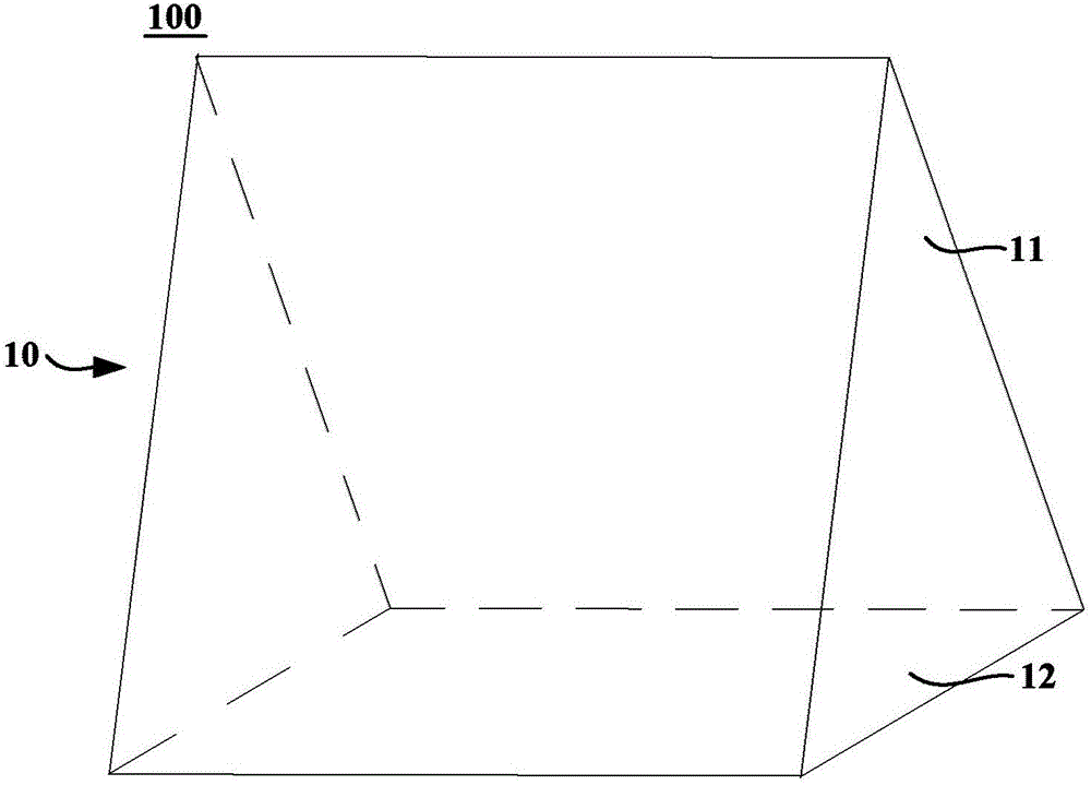
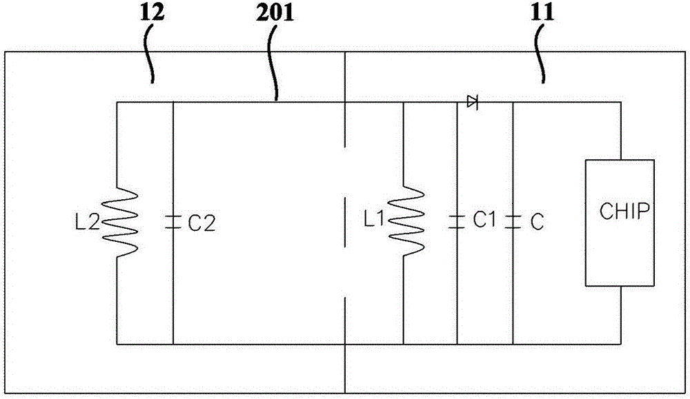
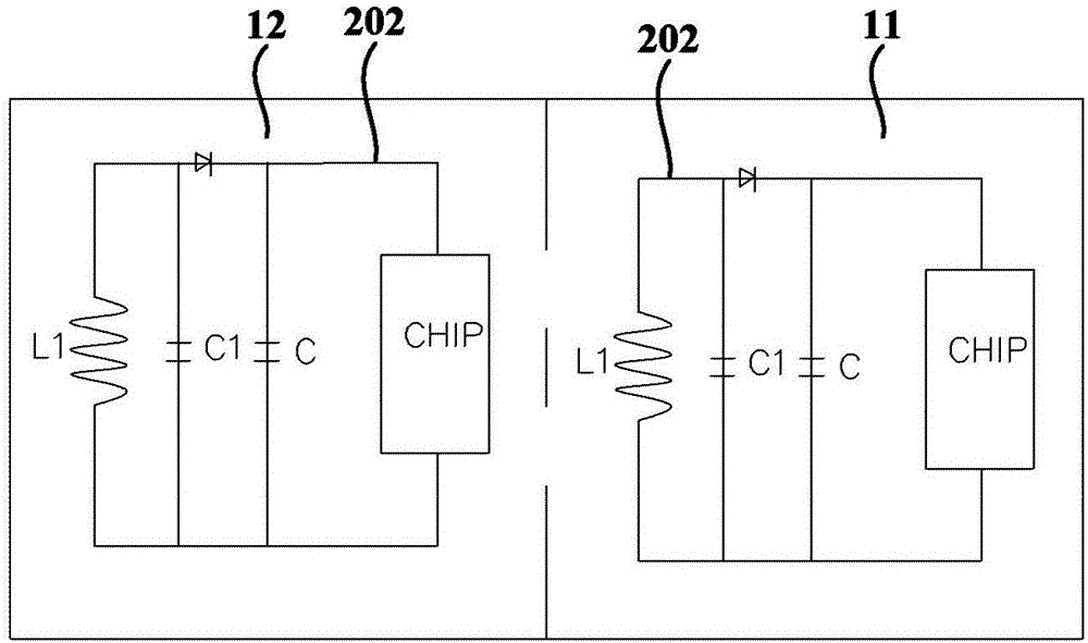
[0032] In the embodiment of the present invention, the RFID tag device may generally include a support and at least one RFID tag loop disposed on the support. As those skilled in the art can realize, the RFID tag circuit usually includes an IC chip and an oscillation circuit composed of an antenna coil and a capacitor. The antenna coil is used to receive the signal sent by the reader and transmit the required data back to the reader.

[0033] In particular, the aforementioned at least one RFID tag loop comprises at least two antenna coils, wherein each antenna coil is located on a different surface of said polyhedral structure. That is to say, each antenna coil is on one surface of the polyhedron structure, and any two antenna coils are not on the same plane of the polyhedron structure. The present invention arranges at least one RFID tag loop with at least two antenna coils on a support with a polyhedron structure, and makes each antenna coil on a different surface of the po...


PUM


Abstract

The invention provides an RFID tag apparatus. The apparatus comprises a support part with a polyhedral structure, and at least one RFID tag loop arranged on the support part and comprising at least two antenna coils, wherein the antenna coils are located on different surfaces of the polyhedral structure. According to the RFID tag apparatus, any two antenna coils can be arranged at an acute angle or an obtuse angle in space, so that planes where any two antenna coils are located are prevented from being perpendicular or parallel in space, electromagnetic wave emission directions of the at least one antenna coil and an antenna of a reader can be ensured not to be perpendicular, the phenomenon of a signal blind area can be effectively avoided, and the tag reading efficiency is improved.

Description

technical field [0001] The invention relates to radio frequency identification technology, in particular to an RFID tag device. Background technique [0002] Radio Frequency Identification (RFID) is a wireless communication technology that can identify specific targets and read and write related data through radio signals without establishing mechanical or optical contact between the identification system and specific targets. After the tag enters the magnetic field, it receives the radio frequency signal sent by the reader, and sends out the product information stored in the chip (passive tag or passive tag) by virtue of the energy obtained by the induced current, or the tag actively sends a signal of a certain frequency to read After the device reads and decodes the information, it sends it to the central information system for relevant data processing. Considering the cost at present, most of the existing home appliances use passive tags, that is, passive tags. [0003]...

Claims


Application Information

Patent Timeline
Patent Type & Authority Applications(China)
IPC IPC(8): G06K19/077
CPCG06K19/07745
Inventor 李京昌唐松志邹磊
Owner HAIER SMART HOME CO LTD
Learn More