Valve device

A technology of valve device and valve body, which is applied in the direction of valve device, valve details, valve shell structure, etc., can solve the problems of hard seal detection, reduce product production efficiency, etc., improve sealing performance, ensure reliability, and avoid flanging problems Effect

Inactive Publication Date: 2017-06-16
ZHEJIANG SANHUA INTELLIGENT CONTROLS CO LTD
View PDF5 Cites 0 Cited by
  • Summary
  • Abstract
  • Description
  • Claims
  • Application Information

AI Technical Summary

Problems solved by technology

After the valve device is assembled, it is usually necessary to test the sealing performance, and since the sealing ring 17' already exists and has been sealed, it is no longer possible to check the slope 131' of the valve stem 13' and the protrusion 111 of the valve body 11'. ' Whether the hard seal between ' is reliably detected
[0007] 3. Since the valve stem 13' must be installed upwards from the lower end of the valve device, and after the valve stem 13' is assembled, the valve seat 14' needs to be welded to the valve body 11', and in order to prevent the heat generated by welding Damage to the sealing ring 17' requires cooling of the valve body 11', which requires changes to the traditional process and reduces the production efficiency of the product

Method used


Image

  • Valve device
  • Valve device
  • Valve device

Examples


no. 1 approach

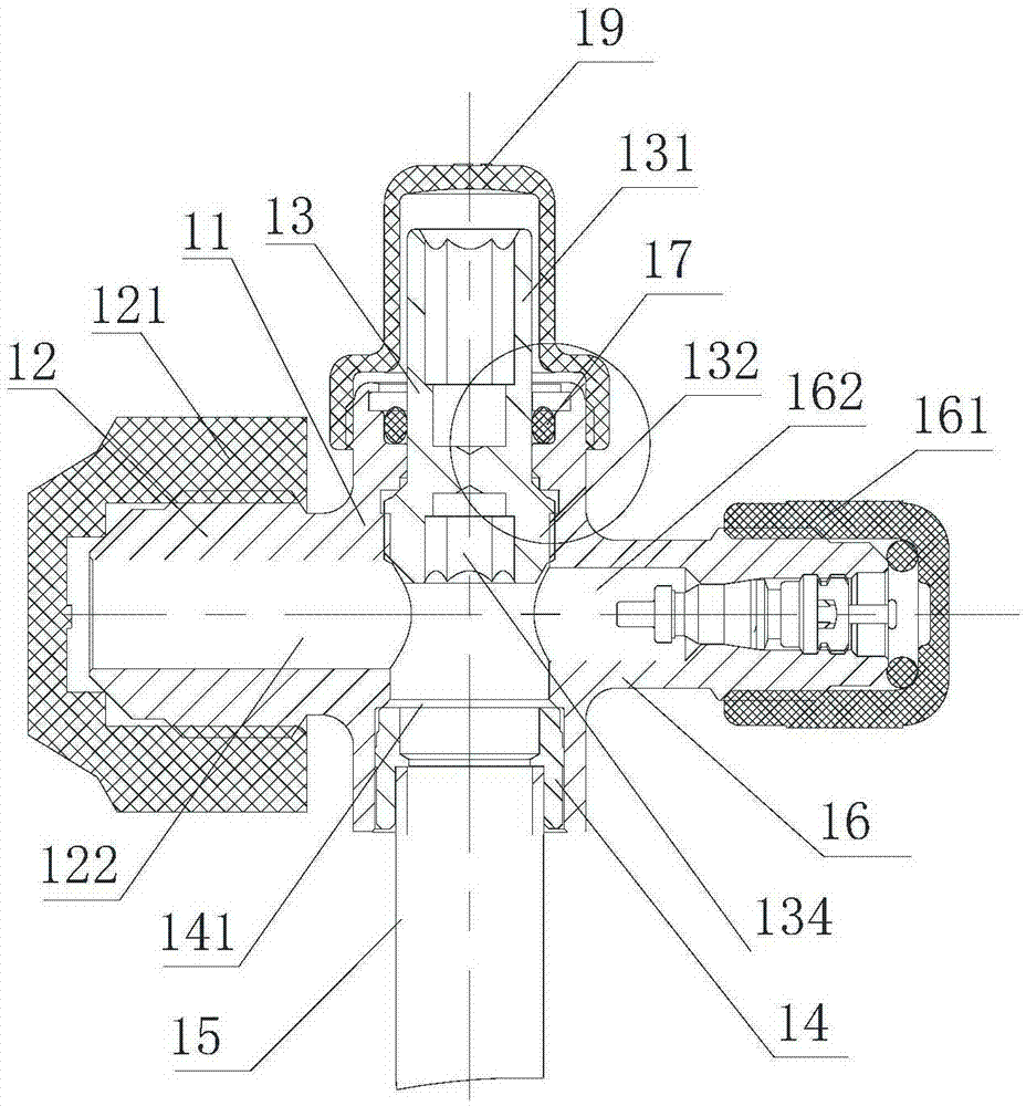
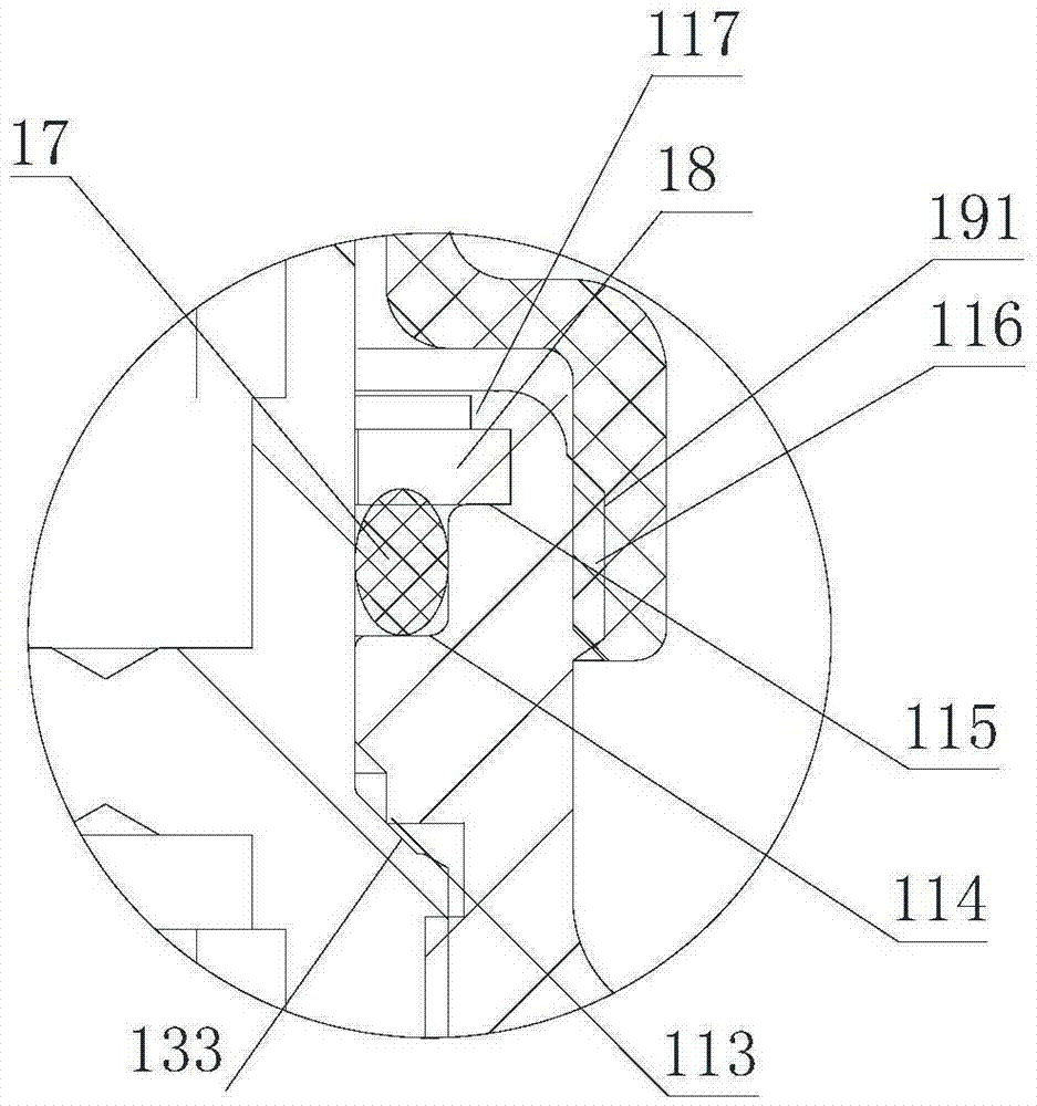
[0032] Please refer to figure 2 , image 3 ,in, figure 2 It is a schematic diagram of the appearance of the valve device of the first embodiment provided by the present invention, image 3 for figure 2 A partial enlargement of the .

[0033] Such as figure 2 As shown, the valve device has a generally cylindrical valve body 11. The valve body 11 can be made by forging or casting, and has a valve cavity 112 inside it, and forms a passage for refrigerant circulation. The lower end of the valve body 11 The opening is used to connect the valve seat 14 and the connecting pipe 15.

[0034] In the valve chamber 112 of the valve body 11, there is provided a generally rod-shaped valve stem 13. The valve stem 13 can be made of materials such as cutting brass or aluminum. The valve stem 13 has a small-diameter section 131 and a large-diameter section 132. The small-diameter section 131 and the large-diameter section 132 are connected by a sealing surface 133 . When the valve st...

no. 2 approach

[0049] Please refer to Figure 4 , Figure 4 It is a schematic structural diagram of the valve device according to the second embodiment of the present invention.

[0050] Since there are some similarities between the second embodiment and the first embodiment, in order to avoid cumbersome repeated descriptions, the following description will focus on the differences between the two. In order to facilitate understanding of the technical solution of the second embodiment, the same reference numerals are used for components having the same structure and function as those of the first embodiment.

[0051] In the second embodiment, the installation part is an annular groove 11a provided on the inner wall of the valve body 11, and the sealing member is placed in the annular groove 11a. During installation, since the sealing component has certain elasticity, it can be placed in the annular groove 11a first. After the valve stem 13 is assembled, the sealing component can form a sea...


PUM


Abstract

The invention provides a valve device which comprises a cylindrical valve body, a valve base and a valve rod. A channel for enabling a refrigerant to be circulated is arranged inside the valve body. The valve base is arranged at the lower end of the valve body and provided with a valve port. The valve rod is arranged inside the valve rod and makes contact with or is separated from the valve port of the valve base through reciprocating motion, and therefore the channel of the valve body is opened or closed. The valve device is characterized in that an installation portion is arranged on the inner wall of the valve body, and a sealing portion is arranged inside the installation portion; the valve rod is installed inside the valve body from the end where the valve base is located; when the valve rod moves upwards to the limit, the valve rod and the valve body are in rigidity seal contact. According to the valve device, the problem that flanging is generated on a sealing component can be effectively avoided, and the sealing performance is improved; meanwhile, the sealing component is installed in the follow-up process, and the influence caused by heat generated when the valve base is welded on the sealing component can be effectively avoided.

Description

technical field [0001] The invention relates to the technical field of refrigerant fluid control components, in particular to a valve device for controlling the on-off of a refrigerant flow path. Background technique [0002] Usually, the valve device is used on the outdoor unit of the air conditioner, and controls the opening and closing of the refrigerant flow path during operation. Please refer to figure 1 , figure 1 It is a sectional view of a valve device in the prior art. Such as figure 1 As shown, the valve device includes a valve body 11', a joint part 12' and a filling part 16' integrally formed with the valve body 11', the valve body 11' has an inner cavity, and the valve stem 13' is arranged in the valve body 11' In the cavity, the valve stem 13' can move up and down in the inner cavity of the valve body 11', thereby opening or closing the valve port 141'. The valve port 141' is set on the valve seat 14', and the valve seat 14' and the valve body 11 'is a spl...

Claims


Application Information

Patent Timeline
Patent Type & Authority Applications(China)
IPC IPC(8): F16K41/02F16K27/02F16K27/08
CPCF16K41/02F16K27/02F16K27/08
Inventor 不公告发明人
Owner ZHEJIANG SANHUA INTELLIGENT CONTROLS CO LTD
Why Eureka
Try Eureka