
Test method and device for simulating interlayer wearing of flexible standpipe armors

A flexible riser and test device technology, applied in the direction of measuring device, strength characteristics, test wear resistance, etc., can solve the problems of inability to evaluate the protection effect of wear-resistant layer, inability to simulate practical applications, etc., and achieve intuitive test results and reasonable design. , The effect of the simple test device

Inactive Publication Date: 2017-06-16
BC P INC CHINA NAT PETROLEUM CORP +1
View PDF2 Cites 4 Cited by
  • Summary
  • Abstract
  • Description
  • Claims
  • Application Information

AI Technical Summary

Problems solved by technology

Therefore, the wear test methods mainly used at present, such as GB / T 12444, GB / T5478, and GB 3960, belong to the material performance test (such as the determination of friction coefficient, etc.), which cannot simulate the actual application situation, nor can it evaluate the wear resistance of the riser. The actual protective effect of the layer

Method used


Image

  • Test method and device for simulating interlayer wearing of flexible standpipe armors
  • Test method and device for simulating interlayer wearing of flexible standpipe armors
  • Test method and device for simulating interlayer wearing of flexible standpipe armors

Examples


Embodiment 1

[0041] Example 1: Testing the Interlaminar Abrasion Resistance of Steel Tensile Armor Layer of Unbonded Flexible Riser

[0042] 1) Sample preparation: use the steel armor wire to prepare 10 straight splines with a length of 10 cm (the cross-section of the sample is the original shape of the steel armor wire, which is a rectangle in this example) as test samples;

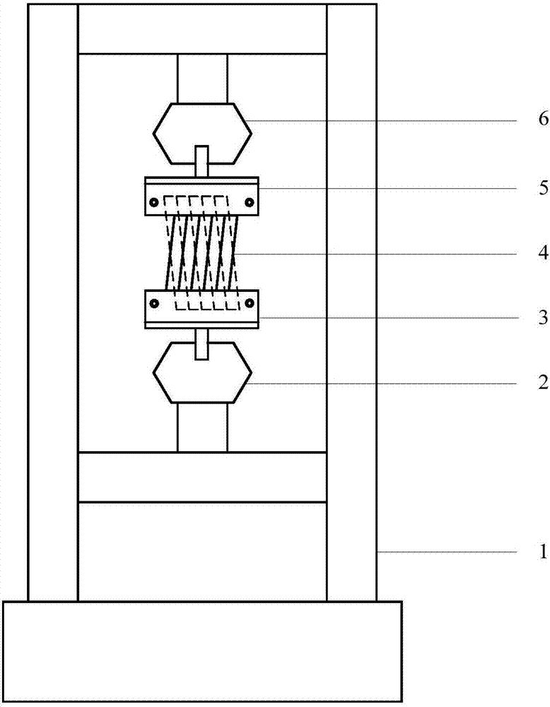
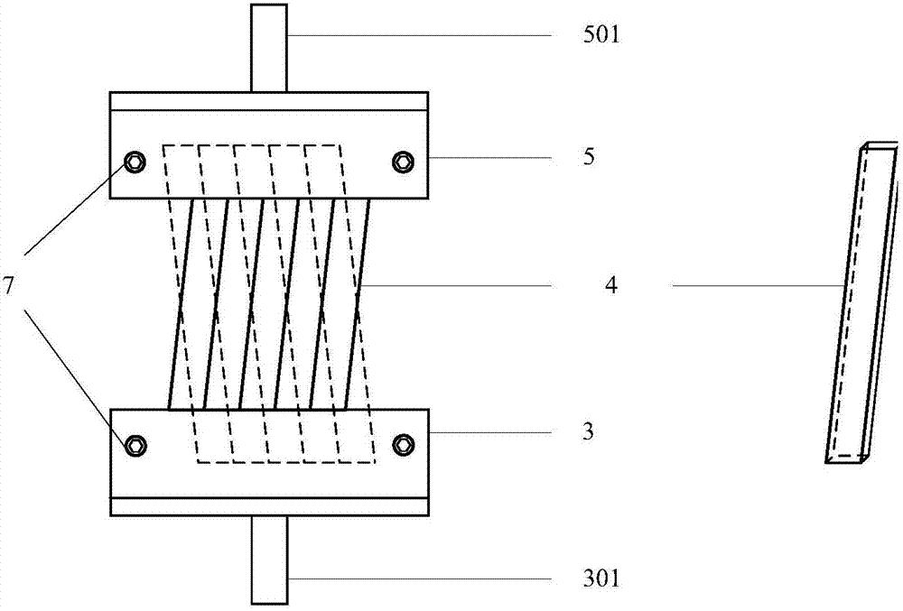
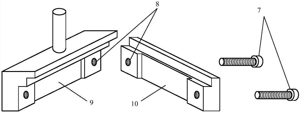
[0043] 2) Sample assembly: Divide the samples into 2 groups, 5 in each group. The ends of each group of samples are closely arranged and even, the two groups of samples cross and overlap, the axial cross angle is 50° (equal to the interlayer winding angle of the steel armor wire in the flexible riser), and the ends of the two groups of samples are placed on the sample In the sample groove of the fixture, and the test fixture is tightly fixed by fastening bolts. It is required that the clamping handles of the two sets of sample fixtures are axially coincident, and the laying direction of each set of samples is at the sa...

Embodiment 2

[0049] Example 2: Test the interlaminar wear resistance of the tensile armor layer of the non-bonded flexible pipe carbon fiber reinforced composite material

[0050] 1) Sample preparation: use the same material and process as the carbon fiber composite armor wire to make 10 straight splines with a length of 15 cm (the cross-section of the sample is equal to the original shape of the armor wire) as test samples;

[0051] 2) Sample assembly: Divide the samples into 2 groups, 5 in each group. Each group of samples is closely arranged and the ends are even. The two groups of samples cross and overlap. The axial cross angle is 60° (equal to the interlayer winding angle of the armor wire in the flexible riser). The ends of the two groups of samples are placed in the sample fixture. Add an appropriate amount of epoxy adhesive in the sample groove, and fix the test fixture tightly by fastening bolts. It is required that the clamping handles of the two sets of sample fixtures overlap ...


PUM


Abstract

The invention relates to a test method and device for simulating the interlayer wearing of flexible standpipe armors. The test device comprises a universal testing machine, a lower testing machine clamp, a lower sample clamp, an upper sample clamp and an upper testing machine clamp. The test method comprises the following steps: 1, sample preparation; 2, sample assembling; 3, sample installation; 4, device preparation; 5, test starting; 6, test ending; and 7, obtaining of a test result. The universal testing machine applies alternate tensile load to the sample clamps, samples are axially elongated and retracted to realize wearing between samples in the same layer and between interlayer samples, the samples are dismounted after test, and the wearing condition is judged by observing damages and detecting the mass loss of the samples per unit length.

Description

[0001] Technical field: [0002] The invention belongs to the technical field of material wear performance testing, and in particular relates to a test method and device for simulating interlayer wear of armor layers of flexible risers. [0003] Background technique: [0004] With the development of the global economy, the demand for oil consumption continues to increase. In the past ten years, due to the high level of onshore oil and gas exploration and development, the scale of newly discovered oil and gas fields is small, and the newly added reserves have contributed to the growth of world oil and gas. Contribution decreased. In contrast, the world's offshore oil and gas exploration is developing rapidly, and its oil and gas production accounts for an increasing proportion of the world's total production. In offshore oil and gas development projects, the submarine pipeline is the channel for submarine oil and gas transportation, also known as the lifeline in the offshore oi...

Claims


Application Information

Patent Timeline
IPC IPC(8): G01N3/04G01N3/06G01N3/56
CPCG01N3/04G01N3/068G01N3/56
Inventor 丁楠戚东涛李厚补邵晓东蔡雪华
Owner BC P INC CHINA NAT PETROLEUM CORP
Learn More