
Trachea casing pipe

A technology of tracheal cannula and extension part, applied in the field of tracheal cannula, can solve the problems of skewed cannula, systemic infection, increased patient pain, etc., and achieves the effects of facilitating cleaning and fixing, expanding nursing space, and increasing protection area

Pending Publication Date: 2017-06-20
张三妹
View PDF6 Cites 1 Cited by
  • Summary
  • Abstract
  • Description
  • Claims
  • Application Information

AI Technical Summary

Problems solved by technology

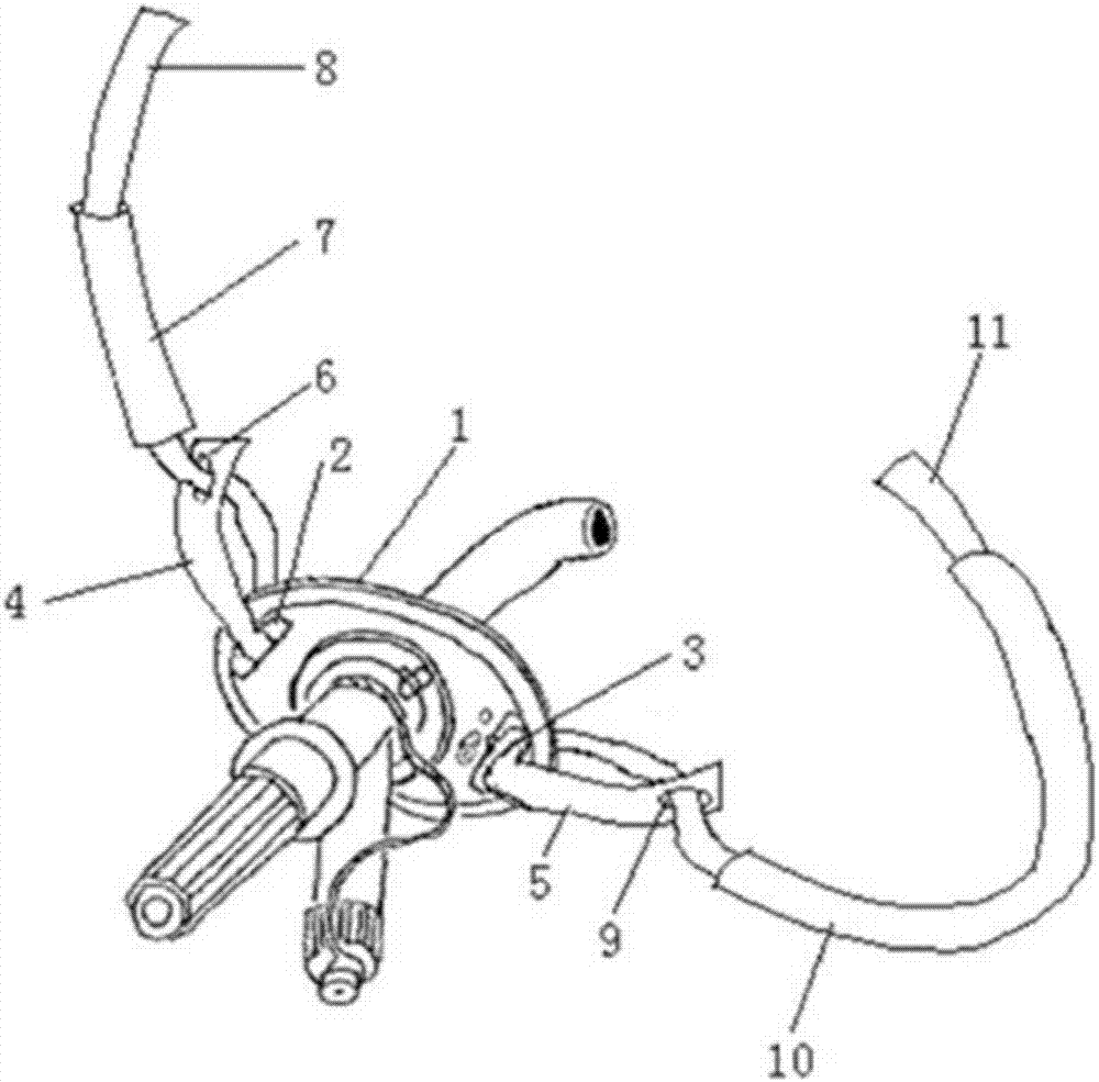
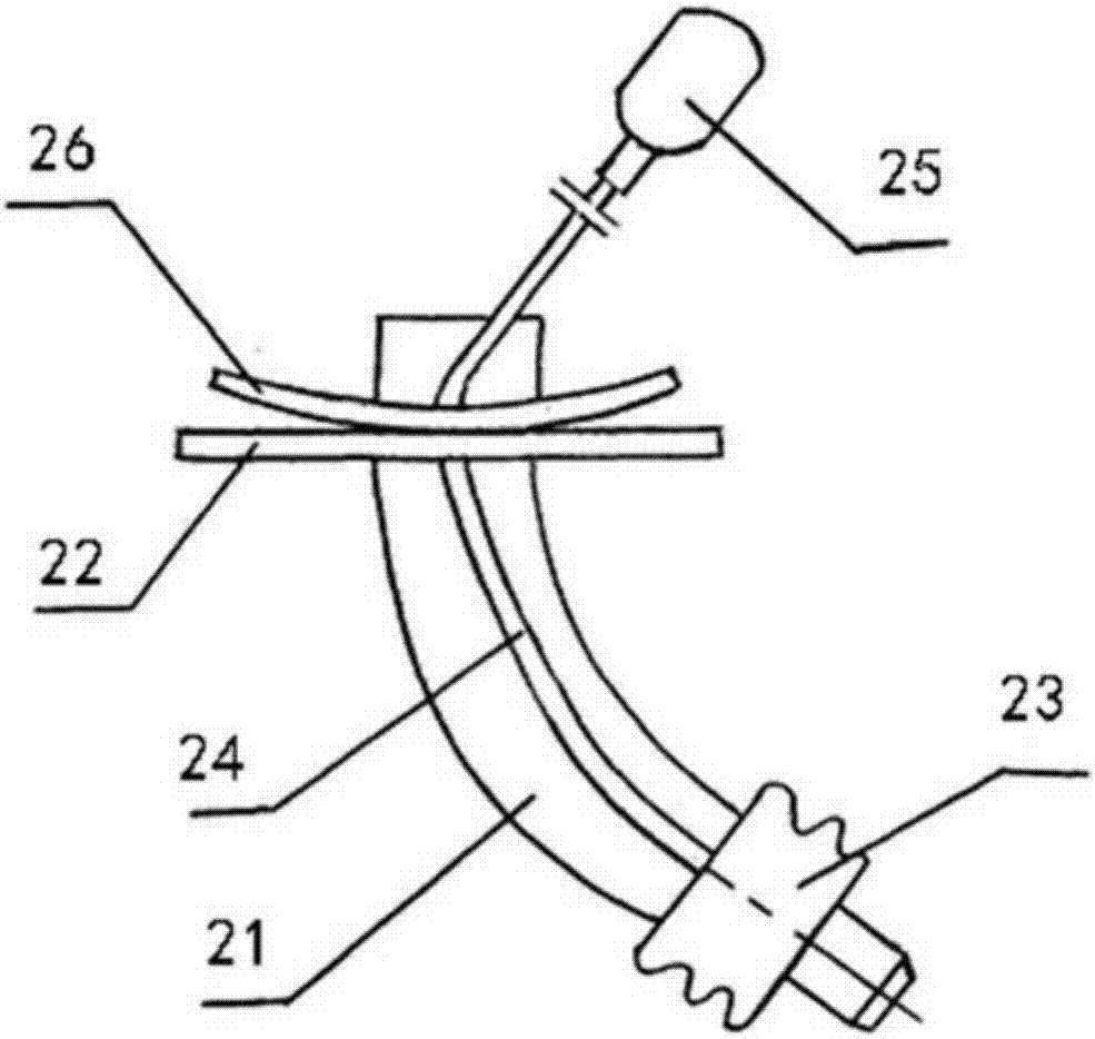
[0007] for figure 2 As shown in the tracheal cannula, although there is a tray on the fixing plate of the cannula body, the skin at the fixing plate still cannot be cleaned and cared for in time, especially in the first 3-5 days after the tracheotomy. There is a lot of bleeding, exudate or sputum, which can easily cause skin redness, damage, and erosion. In severe cases, it will cause systemic infection, increase the incidence of nosocomial infection, and increase the economic burden of patients.
[0008] To sum up, the existing technology cannot improve the nursing space around the tracheal incision, especially the deep surface of the flange of the tracheal cannula, so that the area around 6cm cannot be cleaned and nursed in a timely and effective manner.
Secondly, regardless of the design of the cannula, when operating in the narrow gap between the flange and the skin, the entire tracheal cannula cannot be fully fixed due to the need to partially lift the flange, which will stimulate the patient's cough reflex, increase the patient's pain, and It will make the cannula skew, shift, or even fall out of the cannula, threatening the life of the patient
If the skin around the tracheotomy is to be adequately cared for, the previous design required the cannula to be completely pulled out. This requirement hardly provides effective care for some patients who cannot be extubated.

Method used


Image

  • Trachea casing pipe
  • Trachea casing pipe
  • Trachea casing pipe

Examples


Embodiment Construction

[0037] In order to make the object, technical solution and advantages of the present invention clearer, the present invention will be described in further detail below in conjunction with specific embodiments and with reference to the accompanying drawings.

[0038] It should be noted that, in the drawings or descriptions of the specification, similar or identical parts all use the same figure numbers. Implementations not shown or described in the accompanying drawings are forms known to those of ordinary skill in the art. Additionally, while illustrations of parameters including particular values ​​may be provided herein, it should be understood that the parameters need not be exactly equal to the corresponding values, but rather may approximate the corresponding values ​​within acceptable error margins or design constraints. The directional terms mentioned in the embodiments, such as "upper", "lower", "front", "rear", "left", "right", etc., are only referring to the directio...


PUM


Abstract

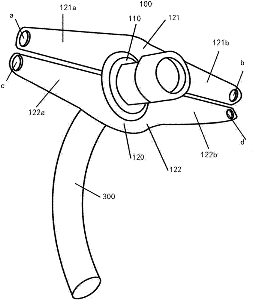
The invention provides a trachea casing pipe. The trachea casing pipe includes a flange plate and a fixing structure, wherein the flange plate includes a flange plate body and two extension parts, the fixing structure includes two parallel fixing straps, and the two parallel fixing straps are connected with the two extension parts respectively and used for fixing the extension parts and further fixing the trachea casing pipe. According to the trachea casing pipe, a person can fully nurse skin around a trachea incision without pulling out the trachea casing pipe, and when throat-mat replacement, auxiliary-material replacement and other operation are conducted on a patient, it is only required to successively lift the flange plate; because the fixing straps remain connected with and fix the trachea casing pipe all the time, the shifting and slipping off of the trachea casing pipe are not caused, the safety is ensured, the operation is convenient, the time and labor are saved, and the workload of nurses is reduced; meanwhile, the trachea casing pipe cannot overly stimulate the cough reflex and the like of the patient, the pain of the patient is reduced, and the comfort of the patient is improved.

Description

technical field [0001] The invention relates to the field of medical instruments, in particular to a tracheal sleeve. Background technique [0002] Tracheotomy (tracheotomy) refers to the incision of the cervical trachea and the insertion of metal, plastic or silicone tracheal tubes to relieve dyspnea caused by laryngeal origin, respiratory dysfunction or retention of lower respiratory tract secretions. Operation. In order to avoid life-threatening acute obstruction of the upper airway caused by displacement or detachment of the tracheal tube, it is usually firmly fixed around the neck with a long cotton strip or a bandage. In practical application, the tracheal tube is required to be fixed with a certain tension, so as to prevent the tracheal tube from loosening, falling off, and endangering life. [0003] The tracheotomy in the neck is a continuous open wound. According to the requirements of the nursing guidelines, it is necessary to check the exudation of the wound and...

Claims


Application Information

Patent Timeline
Patent Type & Authority Applications(China)
IPC IPC(8): A61M16/04
CPCA61M16/0465A61M16/047A61M16/0472
Inventor 田俊王斌全张三妹魏永祥靳荣秀钱波李乐
Owner 张三妹
Learn More