Quick cleaning device for LED lamps

A technology of LED lamps and cleaning devices, which is applied in the directions of dry gas arrangement, cleaning method and utensils, cleaning method using liquid, etc., which can solve the problems of low cleaning efficiency, inconvenient cleaning, long time consumption, etc., and achieve the effect of saving electricity costs

Inactive Publication Date: 2017-06-20
GRACE(NINGBO) LIGHTING CO LTD
View PDF0 Cites 6 Cited by
  • Summary
  • Abstract
  • Description
  • Claims
  • Application Information

AI Technical Summary

Problems solved by technology

[0008] In order to overcome the shortcomings of low cleaning efficiency, long use time and inconvenient cleaning, the technical problem to be solved by

Method used


Image

  • Quick cleaning device for LED lamps
  • Quick cleaning device for LED lamps
  • Quick cleaning device for LED lamps

Examples


Embodiment 1

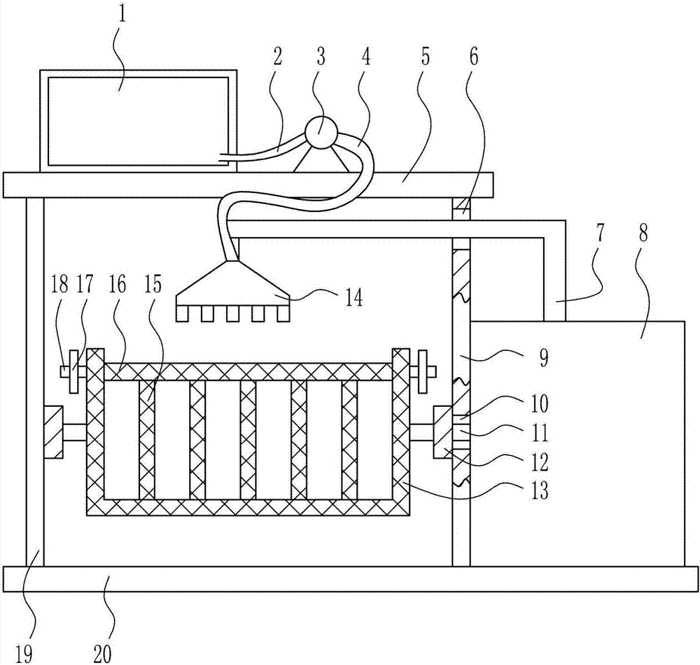
[0032] A quick cleaning device for LED lamps, such as Figure 1-6 As shown, it includes a water tank 1, a first hose 2, a water pump 3, a second hose 4, a top plate 5, a moving rod 7, a rotating and moving mechanism 8, a right bracket 9, a rotating shaft 11, a bearing seat 12, and a cleaning filter frame 13 , nozzle 14, filter screen partition 15, filter screen cover 16, first bolt 17, first screw rod 18, left support 19 and base plate 20, base plate 20 top left and right sides are respectively provided with left support 19 and right support 9, right Have guide hole 6 and the first through hole 10 on the support 9, guide hole 6 is positioned at the first through hole 10 tops, the right side of left support 19 and the left side of right support 9 are provided with bearing seat 12, and bearing seat 12 is provided with Rotating shaft 11 is arranged, and the right side of rotating shaft 11 on the right side passes through first through hole 10, is connected with cleaning filter fram...

Embodiment 2

[0034] A quick cleaning device for LED lamps, such as Figure 1-6 As shown, it includes a water tank 1, a first hose 2, a water pump 3, a second hose 4, a top plate 5, a moving rod 7, a rotating and moving mechanism 8, a right bracket 9, a rotating shaft 11, a bearing seat 12, and a cleaning filter frame 13 , nozzle 14, filter screen partition 15, filter screen cover 16, first bolt 17, first screw rod 18, left support 19 and base plate 20, base plate 20 top left and right sides are respectively provided with left support 19 and right support 9, right Have guide hole 6 and the first through hole 10 on the support 9, guide hole 6 is positioned at the first through hole 10 tops, the right side of left support 19 and the left side of right support 9 are provided with bearing seat 12, and bearing seat 12 is provided with Rotating shaft 11 is arranged, and the right side of rotating shaft 11 on the right side passes through first through hole 10, is connected with cleaning filter fr...

Embodiment 3

[0037] A quick cleaning device for LED lamps, such as Figure 1-6 As shown, it includes a water tank 1, a first hose 2, a water pump 3, a second hose 4, a top plate 5, a moving rod 7, a rotating and moving mechanism 8, a right bracket 9, a rotating shaft 11, a bearing seat 12, and a cleaning filter frame 13 , nozzle 14, filter screen partition 15, filter screen cover 16, first bolt 17, first screw rod 18, left support 19 and base plate 20, base plate 20 top left and right sides are respectively provided with left support 19 and right support 9, right Have guide hole 6 and the first through hole 10 on the support 9, guide hole 6 is positioned at the first through hole 10 tops, the right side of left support 19 and the left side of right support 9 are provided with bearing seat 12, and bearing seat 12 is provided with Rotating shaft 11 is arranged, and the right side of rotating shaft 11 on the right side passes through first through hole 10, is connected with cleaning filter fr...


PUM


Abstract

The invention relates to a cleaning device, in particular to a quick cleaning device for LED lamps. The technical problem to be solved by the present invention is to provide an efficient cleaning device for LED lamps with high cleaning efficiency, less time consumption and convenient cleaning. In order to solve the above technical problems, the present invention provides such a quick cleaning device for LED lamps, which includes a water tank, a first hose, a water pump, a second hose, a top plate, a moving rod, a rotating and moving mechanism, a right bracket, a rotating shaft, and a bearing seat, cleaning filter frame, nozzle, etc.; the left and right sides of the top of the bottom plate are respectively provided with a left bracket and a right bracket, and a guide hole and a first through hole are opened on the right bracket, the guide hole is located above the first through hole, and the right side of the left bracket And the left side of right support is provided with bearing block. The invention achieves better cleaning of the LED lamps, can clean the LED lamps in all aspects, makes the cleaning of the LED lamps more thorough, and improves the cleaning efficiency of the LED lamps.

Description

technical field [0001] The invention relates to a cleaning device, in particular to a quick cleaning device for LED lamps. Background technique [0002] LED is the abbreviation of light-emitting diode. Its basic structure is an electroluminescent semiconductor material chip, which is cured on the bracket with silver glue or white glue, and then connected to the chip and the circuit board with silver or gold wires, and then surrounded by epoxy resin. It is sealed with resin to protect the inner core wire, and finally the shell is installed, so the LED lamp has good shock resistance. The field of application involves mobile phones, table lamps, home appliances and other daily household appliances and machinery production. [0003] Light-emitting diode lamps, also known as LED lamps, refer to appliances that can transmit light, distribute and change the light distribution of LED light sources, including all parts and components required to fix and protect LED light sources exc...

Claims


Application Information

Patent Timeline
IPC IPC(8): B08B3/02F26B21/00
CPCB08B3/022F26B21/004
Inventor 张晓艳
Owner GRACE(NINGBO) LIGHTING CO LTD
Why Eureka
Try Eureka