Feeding manipulator of automatic winding machine for electronic transformer elements and using method

A technology for electronic transformers and automatic winding machines, which is applied in the direction of manipulators, program-controlled manipulators, chucks, etc., and can solve the problems of not being able to adapt to the main body performance of the winding machine, unfavorable winding tasks for transformer components, and large deviations in placement positions. , to achieve the effect of improving winding efficiency and quality, avoiding and uncoordinated, and reducing friction

Pending Publication Date: 2022-01-14
CHINA THREE GORGES UNIV
View PDF8 Cites 0 Cited by
  • Summary
  • Abstract
  • Description
  • Claims
  • Application Information

AI Technical Summary

Problems solved by technology

The former has the phenomenon of low efficiency and large deviation of placement position
Since the latter is an independent external device, the use of an independent feeder for clamping and feeding components with irregular shapes and brittle mat

Method used


Image

  • Feeding manipulator of automatic winding machine for electronic transformer elements and using method
  • Feeding manipulator of automatic winding machine for electronic transformer elements and using method
  • Feeding manipulator of automatic winding machine for electronic transformer elements and using method

Examples


Embodiment 1

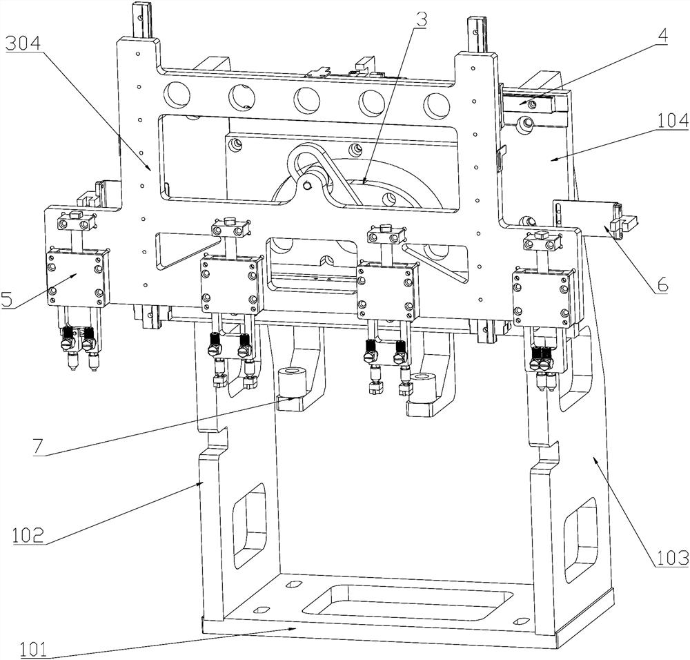
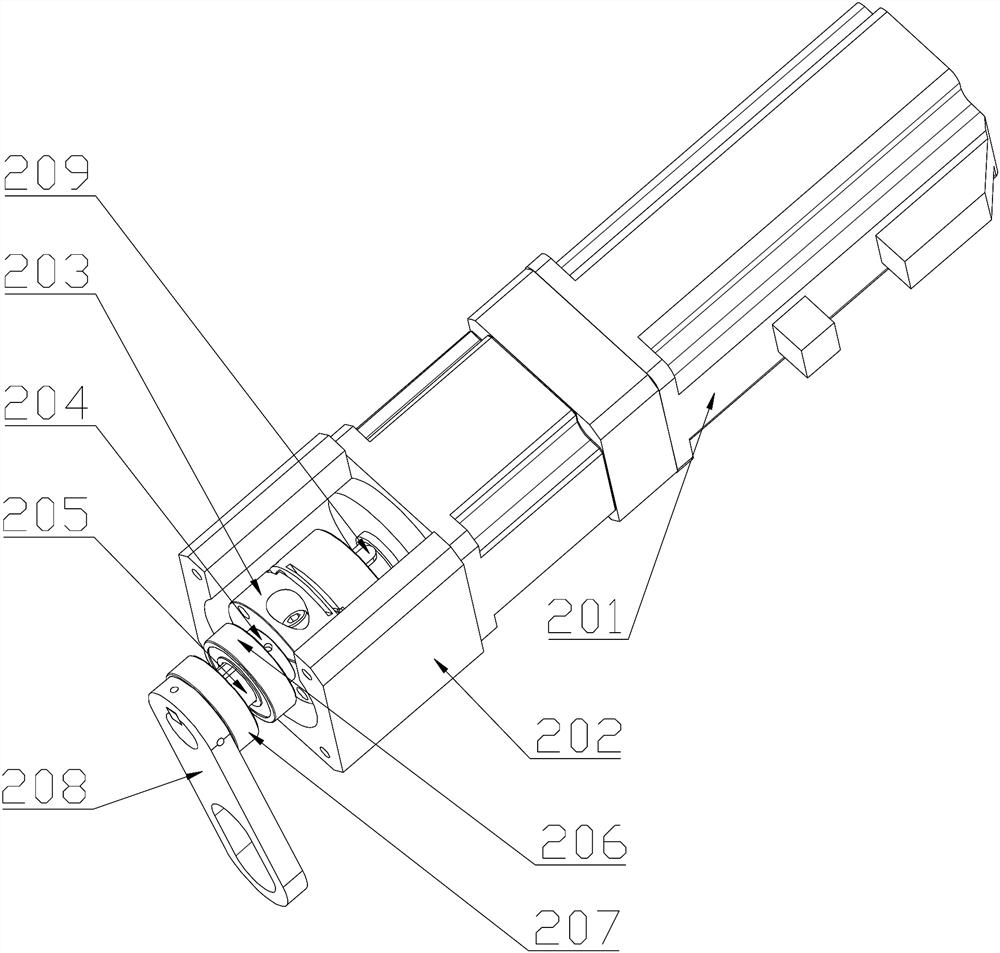
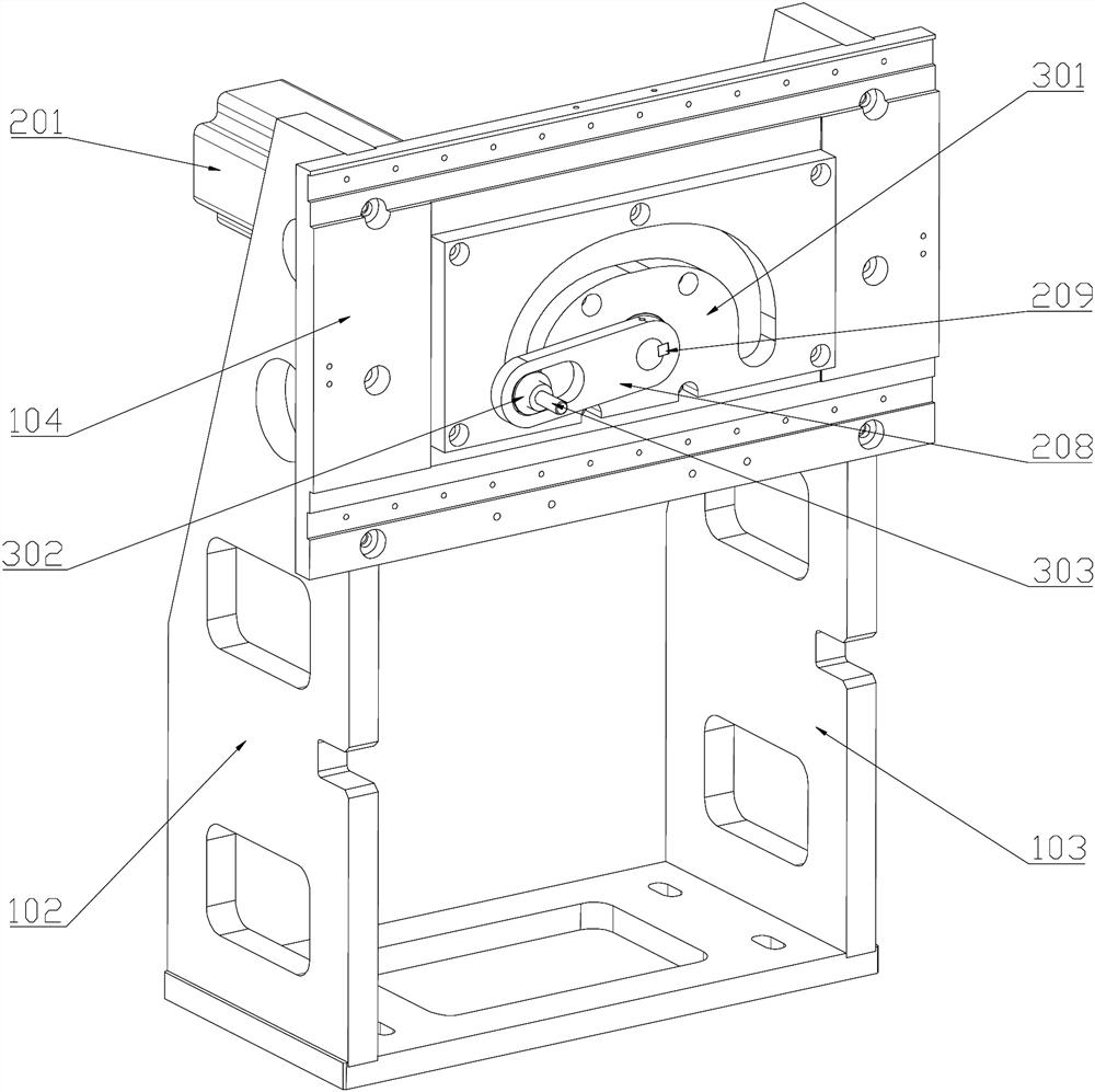
[0048] see Figure 1-9 , the feeding manipulator of the electronic transformer component automatic winding machine, which includes the power unit 2 installed on the back of the support plate 1, the power unit 2 is connected to the U-groove crank 208 through the transmission shaft 205, and the U-groove crank 208 will The power is transmitted to the cam mechanism 3 installed in front of the main mounting plate 104, the cam roller shaft 303 of the cam mechanism 3 is connected with the rotating shaft hole of the movable plate 304, and the loading execution end is driven on the guide rail slider mechanism 4 at the same time. Performing vertical motion and horizontal motion, the joint motion track formed by it is consistent with the motion track of the cam roller 302, so that the manipulator 5 installed on the loading execution end runs according to the preset motion track, and realizes automatic feeding. Through the automatic feeding manipulator with the above structure, automatic ...

Embodiment 2

[0058] The feeding manipulator of the automatic winding machine for electronic transformer components and the method of use thereof include the following steps:

[0059] Step1: When using for the first time, install the feeding manipulator correctly on the feeding station of the electronic transformer component automatic winding machine;

[0060] Step2: placing batches of electronic transformer components with winding wires at the position to be picked by the manipulator 5;

[0061] Step3: Adjust the pneumatic suction nozzle 506 of the feeding manipulator to the initial position, and then adjust the distance between the pneumatic suction nozzle 506 to an appropriate distance;

[0062] Step4: Start the power unit 2, the servo motor drives the transmission shaft 201 to rotate, the U-groove crank connected to the transmission shaft 205 drives the cam mechanism to move along the cam contour; the cam roller shaft drives the movable plate and the manipulator on it according to the p...


PUM


Abstract

The invention relates to a feeding manipulator of an automatic winding machine for electronic transformer elements and a using method. The feeding manipulator comprises a power device mounted on the back of a main mounting plate, the power device is connected with a U-groove crank through a transmission shaft, the U-groove crank drives a cam mechanism in front of the main mounting plate to operate, power is transmitted to a movable plate through the cam mechanism, and under the assistance of a guide rail sliding block mechanism, the movable plate drives the feeding manipulator to achieve automatic feeding and discharging actions according to a preset movement track. According to the feeding manipulator, the feeding efficiency and accuracy of the automatic winding machine for the electronic transformer elements are effectively improved, and due to the design of the cam mechanism and the guide rail sliding block mechanism, the whole feeding manipulator is high in operation stability, low in noise and easy to produce and manufacture.

Description

technical field [0001] The invention relates to the field of production equipment for small electronic transformer components, in particular to a feeding manipulator of an automatic winding machine for electronic transformer components and a use method thereof. Background technique [0002] The winding of the transformer coil is one of the most cumbersome processes in its production process. The main reason is that when delivering the transformer components that need to be wound, most of them still use manual loading. Phenomenon, resulting in low winding efficiency of transformer components, time-consuming and labor-intensive, which not only increases the manufacturing cost, but also affects the development speed of my country's electrical industry from the side. [0003] At present, many electrical component manufacturers still generally use manual loading by operators when producing coils for transformer components, or use a single independent feeding machine for loading. ...

Claims


Application Information

Patent Timeline
IPC IPC(8): B25J9/10B25J15/06
CPCB25J9/10B25J15/0616
Inventor 田启华张学柱付君健杜义贤周祥曼田磊王华蒙永根
Owner CHINA THREE GORGES UNIV
Why Eureka
Try Eureka