Double-worktable-exchange device of laser cutting machine

A technology of double exchange worktable and laser cutting machine, applied in laser welding equipment, manufacturing tools, metal processing equipment, etc., can solve the problems of high cost, inconvenient operation and maintenance, complex structure of double exchange worktable, etc. Interfere with the effect of ensuring consistency

Active Publication Date: 2017-06-20
佛山汇百盛激光科技有限公司
View PDF1 Cites 15 Cited by
  • Summary
  • Abstract
  • Description
  • Claims
  • Application Information

AI Technical Summary

Problems solved by technology

[0008] Aiming at the problems of complex structure, high cost, and inconvenient operation and maintenance of the existing double-exchange worktables of laser cutting machines, the present invention provides a double-exchange worktable device for laser cutting machines, which does not need to be equipped with a lifting mechanism and only operates on the workbench. Reasonable design of the guide rail can complete the exchange between the two workbenches, which greatly simplifies the structure, reduces the manufacturing cost, and has the advantages of convenient operation and simple maintenance

Method used


Image

  • Double-worktable-exchange device of laser cutting machine
  • Double-worktable-exchange device of laser cutting machine
  • Double-worktable-exchange device of laser cutting machine

Examples


Embodiment 1

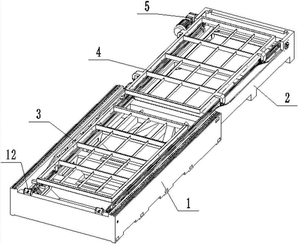
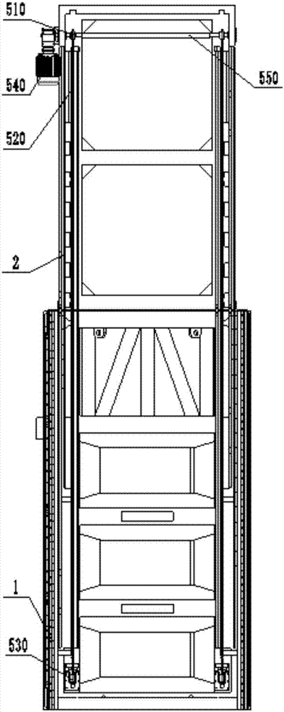
[0067] Such as figure 1 , image 3 , Figure 4 As shown, a laser cutting machine double-exchange workbench device in this embodiment includes a bed composed of a main bed 1 and an auxiliary bed 2, a first workbench 3 and a second workbench 4; wherein, the bed There is a workbench guide rail on it; the first workbench 3 and the second workbench 4 are set on the workbench guide rail, and are driven by a chain transmission mechanism 5 to realize position exchange between the main bed 1 and the auxiliary bed 2 . In this embodiment, the guide rails of the workbench include three guide rails arranged side by side on both sides of the bed body, which are respectively the outer guide rails of the lifting workbench, the inner guide rails of the lift workbench and the guide rails of the translation workbench from the outside to the inside; figure 2 It can be shown that the outer guide rail of the elevating workbench and the inner guide rail of the elevating workbench are both high i...

Embodiment 2

[0074] During the working process of the laser cutting machine, a large amount of smoke will be generated around the bed, and the structure of the bed needs to be designed. Generally, the smoke generated by cutting is sucked in by the suction port arranged around the bed, and discharged through the pipe. . In the actual cutting process, because the air suction port is far away from the high-temperature parts produced by the laser cutting head cutting metal, and the air suction port is relatively scattered, it cannot produce directional and concentrated air flow, so the ventilation effect is often not good; and the bed is used as a supporting part. It is necessary to install guide rails and racks to support the action of the beam, which requires high rigidity, otherwise it will cause post-processing deformation and affect the overall accuracy of the machine tool after assembly. Therefore, this embodiment further improves the structure of the main bed 1 on the basis of the first...


PUM


Abstract

The invention discloses a double-worktable-exchange device of a laser cutting machine, and belongs to the technical field of laser cutting machines. The double-worktable-exchange device comprises a first worktable and a second worktable, wherein the first worktable and the second worktable are arranged on a worktable rail of a lathe bed, and position exchange of the two worktables is achieved through driving of a chain transmission mechanism. The worktable guide rail is divided into a lifting worktable outer guide rail with the middle high and the two ends low, a lifting worktable inner guide rail with the middle high and the two ends low, and a linear horizontal movement worktable guide rail, wherein transition of each middle high section and the corresponding low sections at the two ends is achieved through inclined sections. Two front side wheels at one end of the second worktable are arranged on the lifting worktable outer guide rail, and two rear side wheels at the other end of the second worktable are arranged on the lifting worktable inner guide rail. The first worktable is arranged on the horizontal movement worktable guide rail. The device does not need to be provided with a lifting mechanism, exchange between the two worktables can be completed by only reasonably designing the guide rails where the worktables operate, the structure is greatly simplified, the manufacture cost is reduced, and the double-worktable-exchange device has the beneficial effects of being convenient to operate and easy to maintain.

Description

technical field [0001] The invention belongs to the technical field of laser cutting machines, and more specifically relates to a double exchange workbench device of a laser cutting machine. Background technique [0002] The cutting principle of the laser cutting machine is to focus the laser emitted from the laser into a high-power-density laser beam through the optical path system, and the laser beam is irradiated on the surface of the workpiece to make the workpiece reach the melting point or boiling point. The molten or gasified metal is blown away, and as the relative position of the beam and the workpiece moves, the material finally forms a slit, so as to achieve the purpose of cutting. It has the characteristics of high precision, fast cutting, not limited to cutting pattern restrictions, automatic typesetting to save materials, smooth incision, good effect and low processing cost. [0003] The traditional laser cutting machine workbench is a single workbench. After ...

Claims


Application Information

Patent Timeline
Patent Type & Authority Applications(China)
IPC IPC(8): B23K26/70B23K26/38
CPCB23K26/38B23K26/702
Inventor 梁华隆
Owner 佛山汇百盛激光科技有限公司
Why Eureka
Try Eureka