Automatic feeding device and method for machining lead screw parts

A technology of automatic feeding and parts processing, applied in metal processing and other directions, can solve the problems of high labor intensity, low processing efficiency, low degree of automation, etc., to achieve high degree of automation, improve production efficiency, and promote the effect of automation process.

Pending Publication Date: 2017-06-20
NANJING KANGNI MECHANICAL & ELECTRICAL
View PDF10 Cites 6 Cited by
  • Summary
  • Abstract
  • Description
  • Claims
  • Application Information

AI Technical Summary

Problems solved by technology

[0003] The purpose of the present invention is to overcome the problems of the existing screw parts, which require processing personnel to load and unload materials one by one due to their long length, low processing efficiency, low degree of automation, and high labor intensity.
The automatic feeding device and method for processing screw parts of the present invention has a high degree of automation, solves the problem of loading and unloading artificial screw parts, can improve production efficiency, reduce labor intensity, and further promote the automation process. application prospects

Method used


Image

  • Automatic feeding device and method for machining lead screw parts
  • Automatic feeding device and method for machining lead screw parts
  • Automatic feeding device and method for machining lead screw parts

Examples


Embodiment Construction

[0033] The present invention will be further described below in conjunction with the accompanying drawings.

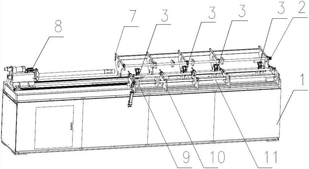
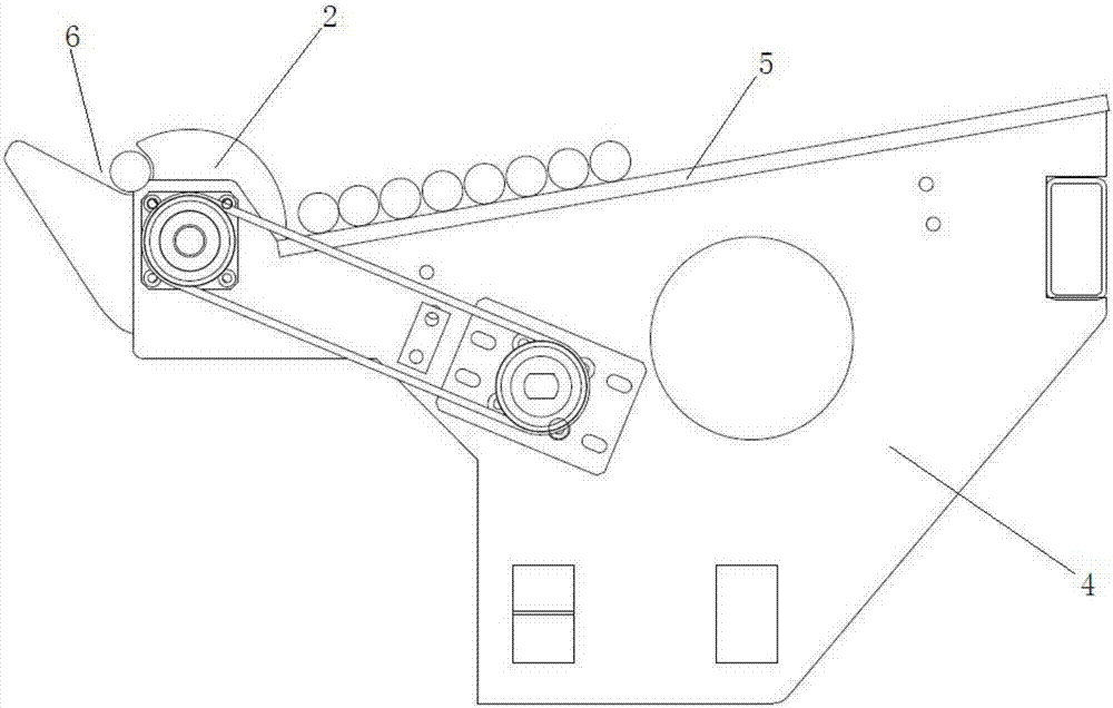
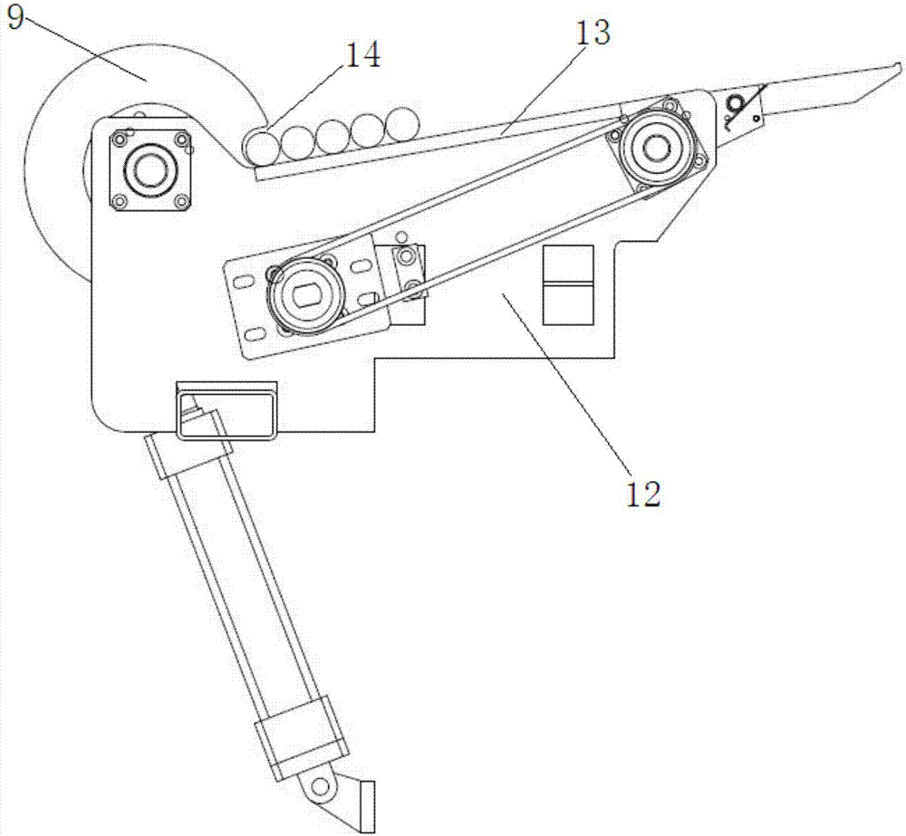
[0034] Such as figure 1 As shown, the automatic feeding device for screw parts processing of the present invention includes a feeding table 1, and the feeding table 1 is equipped with a material distribution and feeding assembly 2, a supporting cylinder assembly 3, and a feeding bracket assembly 7 , feeding trolley assembly 8, material distribution and blanking assembly 9, blanking bracket assembly 10 and blanking assembly 11,

[0035] The feeding bracket assembly 7 and the unloading bracket assembly 10 are respectively arranged on both sides of the feeding table 1, and the feeding trolley assembly 8 is installed on the slide rail on the feeding table 1, and is located on the feeding tray One side of the frame assembly 7 and the blanking bracket assembly 10 is used to clamp the screw parts to be processed or after processing, send them into the machine tool for proces...


PUM


Abstract

The invention discloses an automatic feeding device and method for machining lead screw parts. The automatic feeding device comprises a feeding workbench; the feeding workbench is provided with a distributing and charging assembly, a plurality of supporting cylinder assemblies, a charging bracket assembly, a feeding trolley assembly, a distributing and discharging assembly, a discharging bracket assembly and a discharging assembly; the charging bracket assembly and the discharging bracket assembly are respectively arranged at two sides of the feeding workbench; the feeding trolley assembly is mounted on a sliding rail of the feeding workbench and is used for clamping to-be-machined or machined lead screw parts and feeding the to-be-machined or machined lead screw parts into a machine tool for machining and taking the to-be-machined or machined lead screw parts out of the machine tool; the plurality of supporting cylinder assemblies are mounted at the lower part of the charging bracket assembly; the distributing and charging assembly is mounted at the upper part of the charging bracket assembly; the discharging assembly is mounted on the discharging bracket assembly; and the distributing and discharging assembly is mounted on the discharging bracket assembly; The automatic feeding device is relatively high in automation degree, high in machining efficiency and favorable in application prospect and is used for solving the problem of manual charging and discharging of the lead screw parts and reducing the manual labor intensity.

Description

technical field [0001] The invention relates to the technical field of machining, in particular to an automatic feeding device and method for machining screw parts. Background technique [0002] At present, automatic loading and unloading devices are installed on machine tools to improve working conditions, so they are widely used. However, the structural particularity of screw parts, especially for the screw on the door mechanism of rail transit vehicles, is a slender part with a long length, and both ends need to be processed, and there are many processing procedures. Loading and unloading materials one by one by processing personnel, the processing efficiency is low, the degree of automation is low, and the labor intensity is very high, which needs to be further improved. Contents of the invention [0003] The purpose of the present invention is to overcome the problems of the existing screw parts, which require processing personnel to load and unload one by one due ...

Claims


Application Information

Patent Timeline
Patent Type & Authority Applications(China)
IPC IPC(8): B23Q7/14
CPCB23Q7/141B23Q7/1442B23Q7/1457
Inventor 许慈毕光明樊一鸣
Owner NANJING KANGNI MECHANICAL & ELECTRICAL
Why Eureka
Try Eureka