Machine fabric cutting cutter head

A cutter head and cloth cutting technology, which is applied in the cutting of textile materials, textiles and papermaking, etc., can solve the problems of easy insertion between serrated blades, large installation space, and carbonization of surface cloth, so as to improve the efficiency of cloth cutting and improve the overall strength , to avoid the effect of carbonization

Inactive Publication Date: 2017-06-20
NINGBO ZHENHAI WEICHEN MACHINERY MFG
View PDF0 Cites 0 Cited by
  • Summary
  • Abstract
  • Description
  • Claims
  • Application Information

AI Technical Summary

Problems solved by technology

[0002] The face cloth has a uniform width, and the length of the cloth is different after weaving. It needs to be trimmed on both sides. The current trimming is generally rolled out, and a reciprocating blade or a rotating cutter head is set on both sides to cut off the edge of the cloth. However, the commonly used blades and discs are zigzag, and the blades are elongated. When trimming, they need to reciprocate up and down, and the installation space is large. , cause the surface cloth to drag or get stuck and fail. The cutter head is generally in the shape of a zigzag or toothless disc. The zigzag is easy to jam and fail. The toothless disc cutter will rub at high speed and generate high temperature during use. , resulting in carbonization on both sides of the fabric

Method used


Image

  • Machine fabric cutting cutter head
  • Machine fabric cutting cutter head

Examples


Embodiment Construction

[0012] The technical solutions of the present invention will be further specifically described below through the embodiments and in conjunction with the accompanying drawings.

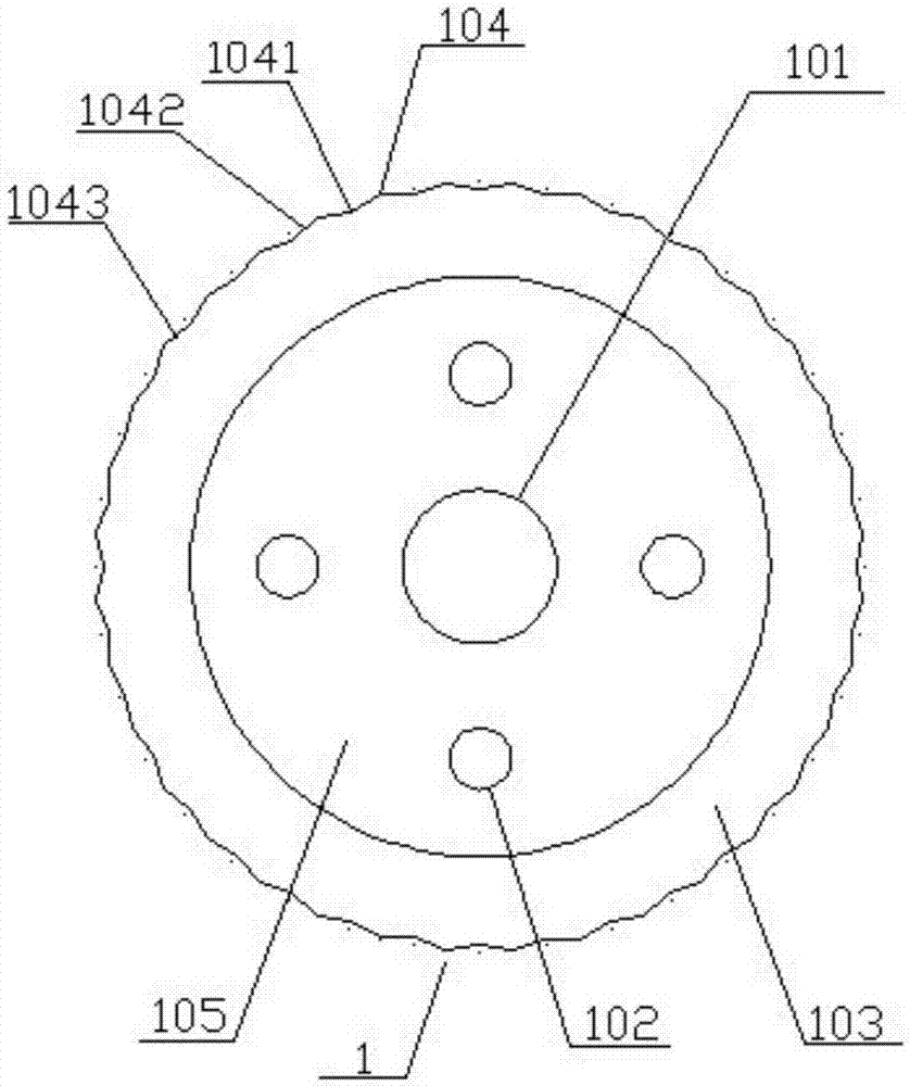
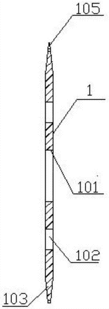
[0013] Such as Figure 1 ~ Figure 2 As shown, the cutter head for machine cloth cutting includes a cutter head 1, the cutter head 1 is a circular sheet, a disc body 105 is arranged in the middle, a mounting hole 101 is arranged in the middle of the disc body 105, bevels 103 are arranged on both sides of the outer side, and The ring is a blade edge 106, four fixing holes 102 are correspondingly arranged on the expansion circumference of the mounting hole 101, the bottom of the hypotenuse 103 is fixed with the disc body 105, and gradually shrinks and becomes thinner, and the blade edge 106 is formed at the top. The blade edge 106 is evenly distributed with several blade tips 104, and a blade valley 1041 is set in the middle of the two adjacent blade tips 104, and the valley bottom of the blade valley 104...


PUM


Abstract

The invention discloses a machine-used cloth cutting cutter head, comprising a cutter head, the cutter head is a circular sheet, a disk body is arranged in the middle, a mounting hole is arranged in the middle of the disk body, hypotenuses are arranged on both sides of the outside, the outer ring is a blade edge, and the installation hole is expanded. Correspondingly set four fixing holes on the circumference, the bottom of the hypotenuse is fixed with the disc body, and gradually shrinks and becomes thinner, the top forms a circle of blade edge, and several blade tips are evenly distributed on the edge of the blade, and a blade valley is set in the middle of two adjacent blade edges , the valley bottom of the blade valley and the left and right adjacent blade tips are provided with blade one and blade two, the fixing hole and the installation hole are concentric circles, the angle of the blade tip is 145-155 degrees, and the angle between blade one and blade two is 155- 165 degrees, blade tip, blade 1, and blade 2 are all sharp cutting edges, and blade 1, blade 2, and blade tip of the present invention form undulating and connected blade edges, which solves the problem of embedding concave-convex teeth in cloth and threads during cloth cutting The dragging of the fabric in the cutter head also avoids the high-temperature carbonization of both sides of the face cloth caused by the disc-shaped cutter head in the cloth cutting process.

Description

technical field [0001] The invention relates to a cutter head for trimming the face cloth, especially a cloth cutting cutter head for a machine. Background technique [0002] The face cloth has a uniform width, and the length of the cloth is different after weaving. It needs to be trimmed on both sides. The current trimming is generally rolled out, and a reciprocating blade or a rotating cutter head is set on both sides to cut off the edge of the cloth. However, the commonly used blades and discs are zigzag, and the blades are elongated. When trimming, they need to reciprocate up and down, and the installation space is large. , cause the surface cloth to drag or get stuck and fail. The cutter head is generally in the shape of a zigzag or toothless disc. The zigzag is easy to jam and fail. The toothless disc cutter will rub at high speed and generate high temperature during use. , resulting in carbonization on both sides of the face cloth. Contents of the invention [000...

Claims


Application Information

Patent Timeline
Patent Type & Authority Applications(China)
IPC IPC(8): D06H7/06
CPCD06H7/06
Inventor 韩娜娜
Owner NINGBO ZHENHAI WEICHEN MACHINERY MFG
Why Eureka
Try Eureka