Novel concrete top die stick

A technology of concrete top and top mold stick, which is applied to the connection parts of formwork/formwork/work frame, structural elements, building components, etc., which can solve the misalignment of top mold stick and cannot control the distance between horizontal ribs and formwork , increasing project costs and other issues, to achieve the effect of stable and reliable structure, convenient binding and fixing, and guaranteed construction quality

Inactive Publication Date: 2017-06-20
SHENYANG JIANZHU UNIVERSITY
View PDF5 Cites 2 Cited by
  • Summary
  • Abstract
  • Description
  • Claims
  • Application Information

AI Technical Summary

Problems solved by technology

[0002] In the construction of reinforced concrete walls, concrete top formwork sticks are generally used to control the thickness of the concrete protective layer. At present, the main concrete top formwork sticks are grooves reserved at both ends of the top formwork sticks, and they are stuck on the horizontal bars during use. The top mold stick is prone to misalignment and cannot play a role in controlling the distance between the horizontal rib and the formwork
Another commonly used top mold stick is to use a steel bar welded with buckles, the buckle is stuck on the horizontal bar, and the thickness of the concrete cover is controlled by the two ends of the steel bar against the steel formwork on both sides, but this kind of top mold stick It will increase the cost of the project. If it is used in the wooden formwork, the two ends of the top mold stick will easily penetrate the wooden formwork

Method used


Image

  • Novel concrete top die stick
  • Novel concrete top die stick

Examples


Embodiment Construction

[0014] The present invention will be described in further detail below in conjunction with the accompanying drawings and specific embodiments, which are explanations rather than limitations of the present invention.

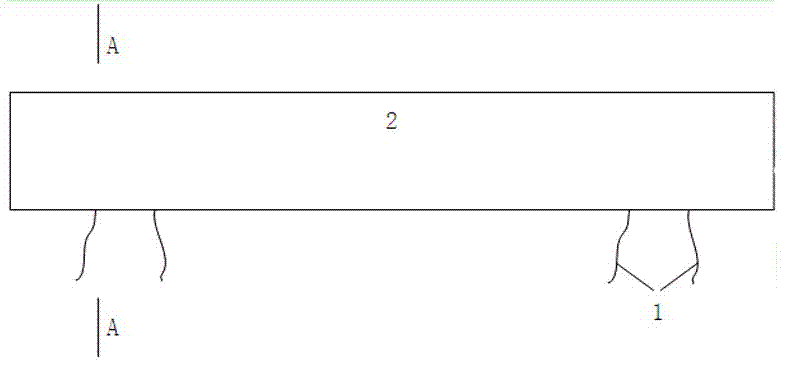
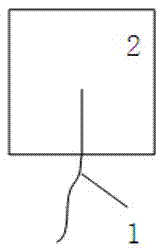
[0015] The invention provides a new type of concrete top mold stick, the overall structure of which is as follows: figure 1 As shown, the cross-sectional view is as figure 2 As shown, it includes a rectangular top mold stick main body 2, two iron wires 1 are pre-embedded symmetrically on both sides of the rectangular top mold stick main body, and the distance between the outermost iron wire and the end of the top mold stick main body on the same side is 1 mm less than the thickness of the concrete protective layer , the distance between 2 iron wires on the same side is 2 ~ 3cm, the length of the iron wire extending outside the main body of the rectangular top mold stick is 6 ~ 8cm, and the diameter of the iron wire is 0.9 ~ 1.6mm; the length of the main body of ...


PUM

PropertyMeasurementUnit
thicknessaaaaaaaaaa
lengthaaaaaaaaaa
diameteraaaaaaaaaa

Abstract

The invention provides a novel concrete top die stick. The novel concrete top die stick comprises a top die stick body, the cross section of the top die stick body is rectangular, iron wires are pre-buried symmetrically at the two sides of the top die stick body, and meanwhile the distance between the outermost wire and the end, the same side of the outermost wire, of the top die stick body is 1 mm smaller than the thickness of a concrete protective layer. The novel concrete top die stick has the advantages of being simple and practical in structure, safe in operation, low in cost and the like, the top die stick body can be accurately fixed on a horizontal rebar during wall rebar binding through the pre-buried iron wires, rebar framework offset can be prevented and the thickness of the concrete protective layer can be controlled, and the construction quality is sufficiently ensured. Compared with an existing concrete top die stick depending on a notch to fix, the novel concrete top die stick is more stable and reliable in structure and more convenient to bind and fix, and compared with a steel top die stick, the novel concrete top die stick is low in cost.

Description

technical field [0001] The invention belongs to the technical field of construction, and in particular relates to a novel concrete top mold stick. Background technique [0002] In the construction of reinforced concrete walls, concrete top formwork sticks are generally used to control the thickness of the concrete protective layer. At present, the main concrete top formwork sticks are grooves reserved at both ends of the top formwork sticks, and they are stuck on the horizontal bars during use. The top mold stick is more prone to misalignment and cannot play a role in controlling the distance between the horizontal rib and the formwork. Another commonly used top mold stick is to use a steel bar welded with buckles, the buckle is stuck on the horizontal bar, and the thickness of the concrete cover is controlled by the two ends of the steel bar against the steel formwork on both sides, but this kind of top mold stick It will increase the cost of the project. If it is used in ...

Claims


Application Information

Patent Timeline
Patent Type & Authority Applications(China)
IPC IPC(8): E04G17/06E04C5/20
CPCE04G17/06E04C5/201
Inventor 刘莉朱耀坤
Owner SHENYANG JIANZHU UNIVERSITY
Why Eureka
Try Eureka