
Control system arranged on projectile body

A control system and projectile technology, applied in the field of control, can solve the problems of high design cost and low cost-effectiveness ratio, and achieve the effect of reducing cost and volume, high cost-effectiveness ratio and low cost

Inactive Publication Date: 2017-06-20
BEIJING AEROSPACE AUTOMATIC CONTROL RES INST
View PDF5 Cites 11 Cited by
  • Summary
  • Abstract
  • Description
  • Claims
  • Application Information

AI Technical Summary

Problems solved by technology

[0004] However, although the 6-degree-of-freedom control method based on the cross-canard rudder used in the prior art can accurately realize the transverse and normal overload correction, the overall design cost is high and the cost-effectiveness ratio is low

Method used


Image

  • Control system arranged on projectile body
  • Control system arranged on projectile body
  • Control system arranged on projectile body

Examples


Embodiment Construction

[0038] In order to make the object, technical solution and advantages of the present invention clearer, the present invention will be further described in detail below with reference to the accompanying drawings and examples.

[0039] This embodiment provides a control system arranged on the projectile body, thereby greatly reducing the cost and volume of the mortar projectile control cabin, and greatly improving the cost-effectiveness ratio.

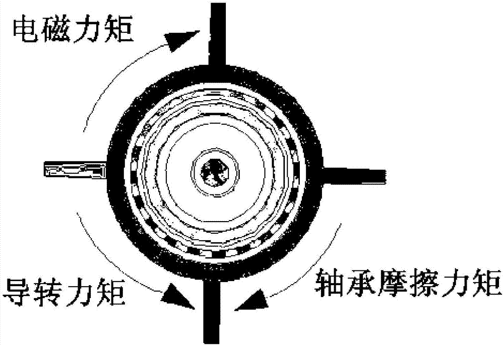
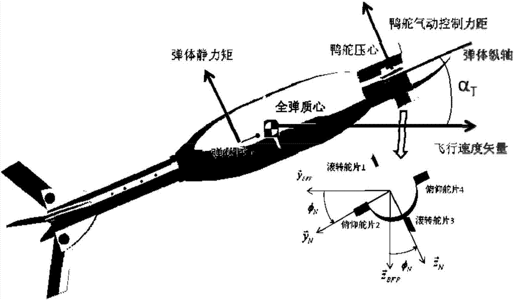
[0040] figure 1 It is a schematic structural diagram of the control system in the embodiment of the present invention, figure 2 It is a structural schematic diagram of the fixed-wing canard and the control assembly in the embodiment of the present invention, image 3 It is a schematic diagram of the principle of the control system in the embodiment of the present invention. Such as Figure 1~3 As shown, the control system provided on the missile body in the embodiment of the present invention mainly includes: fixed wing canards and ...


PUM


Abstract

The invention discloses a control system arranged on a projectile body. The control system comprises a fixed wing canard rudder and a control assembly as a permanent magnet motor and a controller used for controlling the permanent magnet motor, wherein the control assembly is arranged at a control cabin on the front part of the projectile body; the permanent magnet motor comprises a rotor, a stator and a bearing; the stator is fixedly arranged on a longitudinal shaft of the projectile body; the rotor is arranged at the periphery of the stator; the rotor and the stator are connected through the bearing; the controller is arranged in the control cabin, and is connected with the longitudinal shaft through a control circuit; the fixed wing canard rudder is arranged on the outer wall of the rotor, and comprises two pairs of rudder plates with a fixed rudder angle; one pair of rudder plates is reverse in deflecting direction, and is used for providing external pneumatic angular moment needed for reverse rotation of the canard rudder; and the other pair of the rudder plates is the same in deflecting direction, and is used for providing pneumatic-control moment vector of posture adjustment of the projectile body. The control system arranged on the projectile body is arranged, so that cost and the size of the control cabinet of a mortar projectile can be greatly reduced, and a cost-benefit ratio is greatly increased.

Description

technical field [0001] The invention relates to the technical field of control, in particular to a control system arranged on a projectile. Background technique [0002] When traditional tactical missiles fly in the atmosphere, they are generally controlled by servo mechanisms to control air rudders. However, this method is not suitable for applications where the internal space of the missile body is particularly narrow and the cost is low. For example, it cannot be applied to mortars. shells. [0003] Mortar shells in the prior art calculate the firing angle and firing muzzle velocity of the mortar according to the target range and firing table before launching. Under ideal and error-free conditions, mortar shells can fly to the target according to a parabolic trajectory after being fired. However, in the actual application environment, due to the influence of various elements of ballistic error, target maneuvering and various random disturbances (such as projectile proce...

Claims


Application Information

Patent Timeline
IPC IPC(8): F42B10/64
CPCF42B10/64
Inventor 张衍儒肖练刚陈文辉张喆郭城孙凯白璐邱奕
Owner BEIJING AEROSPACE AUTOMATIC CONTROL RES INST
Learn More