Design method of frameless splicing optical window

A technology of optical window and design method, which is applied in the field of optical window, can solve problems such as not detailed description, and achieve the effect of improving the ability of detection and recognition

Active Publication Date: 2019-03-29
西安应用光学研究所
View PDF9 Cites 0 Cited by
  • Summary
  • Abstract
  • Description
  • Claims
  • Application Information

AI Technical Summary

Problems solved by technology

The patent does not detail the optimization method of the optical window splicing model to adapt to supersonic flight conditions

Method used


Image

  • Design method of frameless splicing optical window
  • Design method of frameless splicing optical window
  • Design method of frameless splicing optical window

Examples


Embodiment Construction

[0021] The present invention will be further described in detail below in conjunction with the accompanying drawings and preferred embodiments.

[0022] The purpose of the present invention is to provide a frameless splicing design method for the optical window whose maximum diagonal size is greater than 500mm on the airborne optoelectronic equipment flying at supersonic speed, without the support of structural parts at the splicing place.

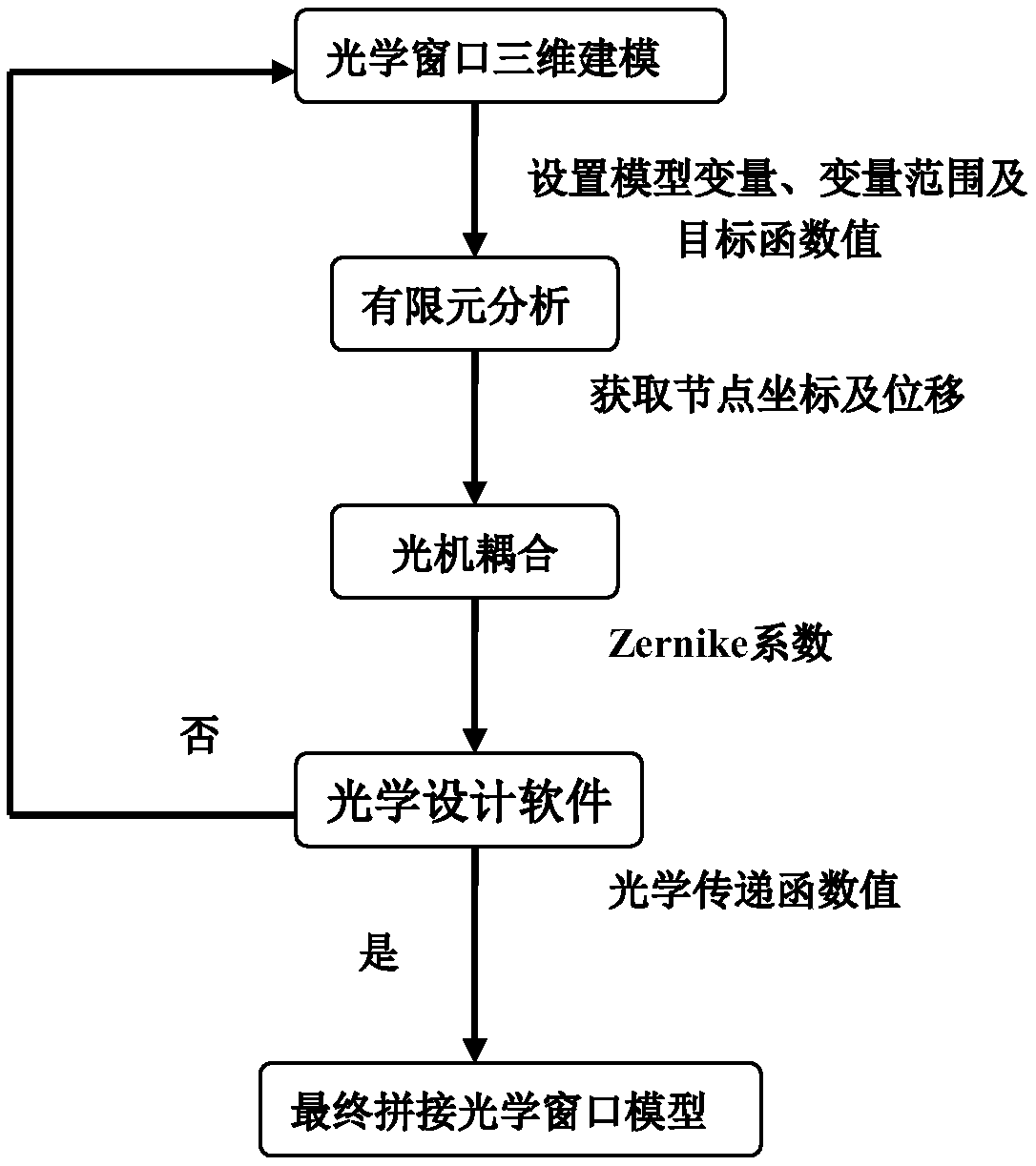
[0023] Such as image 3 As shown, it specifically includes the following steps:

[0024] Step 1: Calculate the overall size of the optical window that satisfies the effective total field of view of the load according to the system's index requirements, and use multiple optical windows for splicing;

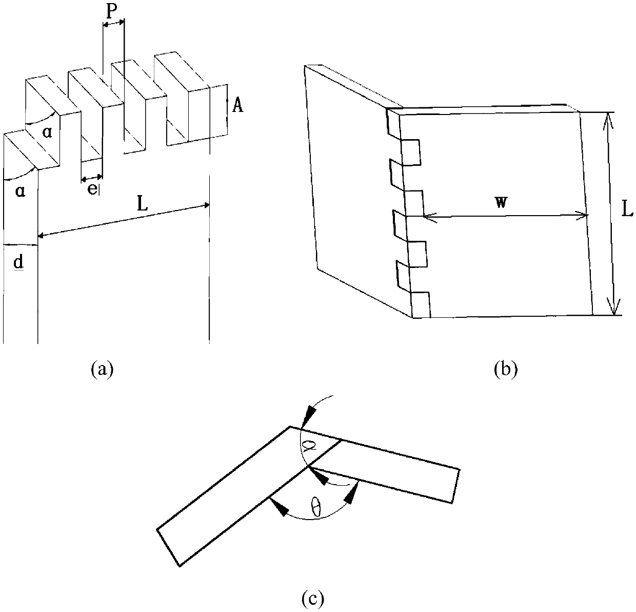
[0025] Step 2: For any two adjacent optical windows that need to be spliced, use the following method to design the splicing parameters of the optical windows:

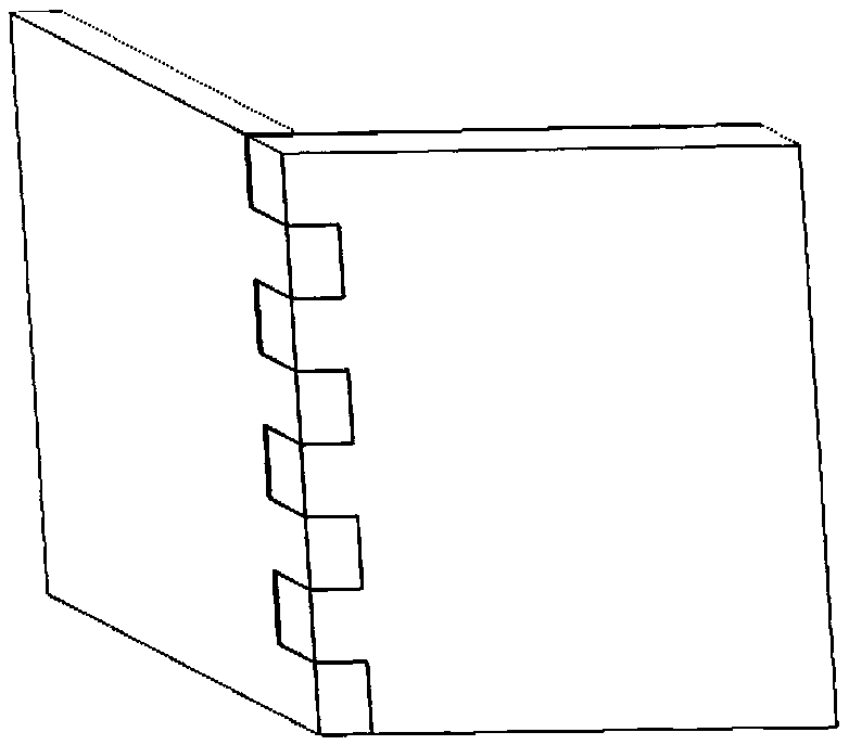
[0026] Step 2.1: The splicing of the two spliced ​​optical windows is spliced ​...


PUM


Abstract

The invention proposes a frameless splicing type optical window design method. A plurality of optical windows are spliced to form an optical window appearance dimension meeting an effective total field of view of a load; models of the splicing parts of the spliced optical windows are in a rectangular tooth mode; finite element simulation and optimization are carried out on the optical window models at the spliced parts according to a using environment of the spliced optical window; model variables of the spliced parts of the spliced optical windows are changed continuously and repeated iteration and optimization are carried out until an objective function value is reached. Therefore, an optical window design with the maximum dimension of the diagonal line larger than 500mm is realized; and a frameless splicing design method not needing a structural component for support at a spliced part can be provided for airborne optoelectronic equipment in supersonic flight.

Description

technical field [0001] The invention belongs to the field of optical windows, and mainly relates to a frameless splicing design of at least two optical windows. Background technique [0002] When the aircraft flies at supersonic speed in the atmosphere, the fuselage and the optical window interact with the airflow to form a variety of complex flow field structures such as shock waves, expansion waves, and turbulent boundary layers, resulting in the occurrence of density, pressure, and temperature fields around it. Variety. The presence of these non-uniformities degrades the performance of the optical window. In addition, in order to improve its own detection and identification capabilities, the airborne optoelectronic system flying at supersonic speed requires increasing the aperture of the optical system in order to obtain more energy information. Optical windows with a maximum diagonal size greater than 500mm are often limited by the size of the optical material. In orde...

Claims


Application Information

Patent Timeline
Patent Type & Authority Patents(China)
IPC IPC(8): G02B27/00
CPCG02B27/0012
Inventor 王楠茜何玉兰李元姜霄白强华康文莉韩梅
Owner 西安应用光学研究所
Why Eureka
Try Eureka