Charging device of storage battery
A charging device and storage battery technology, applied in battery circuit devices, circuit devices, arrangement of multiple synchronous batteries, etc., can solve problems such as complex circuit structure, achieve simple circuit structure, and improve service life
- Summary
- Abstract
- Description
- Claims
- Application Information
AI Technical Summary
Problems solved by technology
Method used
Image
Examples
Embodiment 1
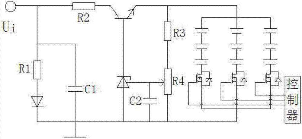
[0017] Such as figure 1 The shown battery charging device includes a battery pack and a charging circuit connected to the battery pack. The charging circuit includes a triode and a controllable precision voltage regulator tl431. The collector of the triode is connected to the input terminal through a second resistor. connected and the input terminal is connected to the anode of the diode through the first resistor, the cathode of the diode is grounded, the cathode of the tl431 is connected to the base of the triode and the anode is grounded, the emitter of the triode is connected to the The reference electrode of the tl431 is connected to the voltage dividing terminal of the voltage dividing circuit, the anode of the battery pack is connected to the emitter of the triode and the cathode is grounded.
Embodiment 2
[0019] This embodiment is optimized on the basis of the above embodiments, the voltage divider circuit includes a third resistor and a fourth resistor connected in series, the fourth resistor is an adjustable resistor, and its adjustable end constitutes a voltage divider end .
[0020] In order to reduce the influence of external interference, a second capacitor is connected between the reference pole of the tl431 and the ground.
[0021] A first capacitor is connected between the input terminal and the ground.
Embodiment 3
[0023] Existing batteries generally use a battery pack composed of multiple batteries to meet the requirements of large capacity. It uses a plurality of batteries connected in parallel to form a battery pack that meets a certain capacity requirement, and then multiple battery packs are connected in series to form a large-capacity battery that meets a certain capacity and a certain rated voltage. However, there is a disadvantage of using this method, that is, if the parameters in a single battery pack do not match, such as internal resistance, when the battery stops working, since a single battery pack is composed of multiple batteries connected in parallel, a discharge circuit must be formed in the battery pack. After a period of time, the battery capacity will drop significantly, which will damage the service life of the battery. When the parameters of each battery in the battery pack do not match, the loss will be more obvious. In order to solve the above technical problems,...
PUM
 Abstract
Description
Claims
Application Information
 - R&D
- Intellectual Property
- Life Sciences
- Materials
- Tech Scout
- Unparalleled Data Quality
- Higher Quality Content
- 60% Fewer Hallucinations
Browse by: Latest US Patents, China's latest patents, Technical Efficacy Thesaurus, Application Domain, Technology Topic, Popular Technical Reports.
© 2025 PatSnap. All rights reserved.Legal|Privacy policy|Modern Slavery Act Transparency Statement|Sitemap|About US| Contact US: help@patsnap.com

