
Optimization control method for charging and discharging process of LCC type wireless charging system

A charging and discharging process, wireless charging technology, applied to battery circuit devices, control/regulation systems, high-efficiency power electronics conversion, etc., can solve problems such as increased active loss, reduced power factor, reduced overall system efficiency, etc., to achieve reduced conduction pass loss and switching loss, achieve constant voltage charging, and improve transmission efficiency

Pending Publication Date: 2022-03-01
JIANGSU ELECTRIC POWER CO +2
View PDF0 Cites 0 Cited by
  • Summary
  • Abstract
  • Description
  • Claims
  • Application Information

AI Technical Summary

Problems solved by technology

However, when the vehicle battery voltage changes greatly and is used in two special stages of battery charging, the voltage and current phases of the high-frequency inverter full-bridge output on the DC bus side of the system and the vehicle battery side produce a large phase shift. This reduces the power factor of the system, increases the active power loss of the system, and reduces the overall efficiency of the system

Method used


Image

  • Optimization control method for charging and discharging process of LCC type wireless charging system
  • Optimization control method for charging and discharging process of LCC type wireless charging system
  • Optimization control method for charging and discharging process of LCC type wireless charging system

Examples


Embodiment Construction

[0030] In order to enable those skilled in the art to better understand the solutions of the present invention, the following will clearly and completely describe the technical solutions in the embodiments of the present invention in conjunction with the drawings in the embodiments of the present invention. Obviously, the described embodiments are only It is an embodiment of a part of the present invention, but not all embodiments. Based on the embodiments of the present invention, all other embodiments obtained by persons of ordinary skill in the art without making creative efforts shall fall within the protection scope of the present invention.

[0031] It should be noted that the terms "first" and "second" in the description and claims of the present invention and the above drawings are used to distinguish similar objects, but not necessarily used to describe a specific sequence or sequence. It is to be understood that the data so used are interchangeable under appropriate ...


PUM


Abstract

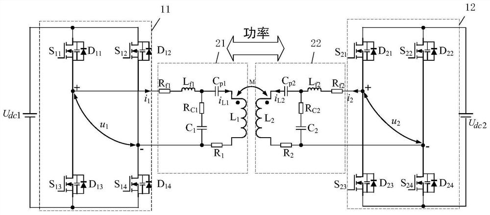
The invention discloses an optimal control method for the charging and discharging process of an LCC type wireless charging system, and the method comprises the steps: keeping the internal phase shift angle alpha 1 of a first H bridge and the internal phase shift angle alpha 2 of a second H bridge unchanged when the wireless charging system is in a constant-current charging state, the working frequency f of the wireless charging system and the external phase shift angle between the two are adjusted, so that the switching tubes in the H bridges on the two sides are zero-voltage switching tubes; when the wireless charging system is in a constant-voltage charging state, the working frequency f of the wireless charging system is kept unchanged, and the internal phase shift angle alpha1 of the first H bridge, the internal phase shift angle alpha2 of the second H bridge and the external phase shift angle between the two are adjusted, so that the switching tubes in the H bridges on the two sides are zero-voltage switching tubes. According to the optimal control method for the charging and discharging process of the LCC type wireless charging system, the conduction loss and the switching loss of the system are reduced, and the transmission efficiency of the system is improved.

Description

technical field [0001] The invention relates to the technical field of electric vehicle wireless charging, in particular to an optimization control method for the charging and discharging process of an LCC type wireless charging system. Background technique [0002] In recent years, with the development of science and technology, wireless charging (Wireless Power Transfer, WPT) has gradually replaced wired charging and entered the market. Because the WPT system has the advantages of high security, high reliability and flexibility, it has attracted the close attention of many scholars and people in the industry at home and abroad. Among them, the bidirectional WPT (Bidirectional WPT, BWPT) system can make the energy transfer between the two systems The exchange can enable electric vehicles to participate in the deployment of the power grid, and can realize optimized operation functions such as orderly charging and peak shaving and valley filling. The convenience provided by t...

Claims


Application Information

Patent Timeline
IPC IPC(8): H02J50/12H02J7/06H02J7/00H02M3/335H02M1/088
CPCH02J50/12H02J7/06H02J7/0063H02M3/3353H02M1/088Y02B70/10Y02T10/7072Y02T90/14Y02T10/70
Inventor 韩克勤李亚飞钱科军刘乙张晓明谢鹰郑众吕晓飞武迪古铭吴克辰
Owner JIANGSU ELECTRIC POWER CO
Learn More