Supercharge Your Innovation With Domain-Expert AI Agents!

Pressure vessel

A technology for pressure vessels and cylinders, which is applied in the field of pressure vessels with non-central joints, and can solve problems such as the failure of the function of the joints to control the liquid position in the vessel, the increase in the amount of welding deposited metal filling, and the huge difference in heat input. Achieve the effect of increasing the groove processing effect, improving the welding quality and reducing the processing cost

Active Publication Date: 2017-06-23
HARBIN ELECTRIC CORP QINHUANGDAO HEAVY EQUIP
View PDF7 Cites 2 Cited by
  • Summary
  • Abstract
  • Description
  • Claims
  • Application Information

AI Technical Summary

Problems solved by technology

[0002] Non-central joint is a common structural form in pressure vessel products. For the welding groove between the joint and the cylinder, after the conventional welding groove is processed by the non-central joint and the cylinder, the connection between the joint and the cylinder The space at least 1 / 4 of the circumference of the groove at the acute angle is too large, resulting in a lot of welding deposit metal filling during the welding process; on the other side symmetrical to it, the welding deposit metal filling is less, resulting in There is a huge difference in heat input during the welding process on both sides of the nozzle, and this phenomenon increases with the increase of the distance between the nozzle and the axial center of the cylinder
Therefore, such a groove form causes the following two serious problems after the non-central joint and the cylinder are welded:
[0003] 1) The connecting pipe is seriously deformed, and the connecting pipe is deformed toward the center of the cylinder. When the connecting pipe is welded to the external pipeline or connected to the flange, it will cause misalignment and cannot be carried out; Functional failure of the internal liquid position;
[0004] 2) The cylinder is deformed. If the thickness of the cylinder is thin, it will cause a large deformation of the cylinder at the welding position

Method used


Image

  • Pressure vessel
  • Pressure vessel
  • Pressure vessel

Examples


Embodiment Construction

[0059] Hereinafter, the present invention will be further described in detail through the drawings and embodiments. Through these descriptions, the characteristics and advantages of the present invention will become clearer.

[0060] The dedicated word "exemplary" here means "serving as an example, embodiment, or illustration." Any embodiment described herein as "exemplary" need not be construed as being superior or better than other embodiments. Although various aspects of the embodiments are shown in the drawings, unless otherwise noted, the drawings are not necessarily drawn to scale.

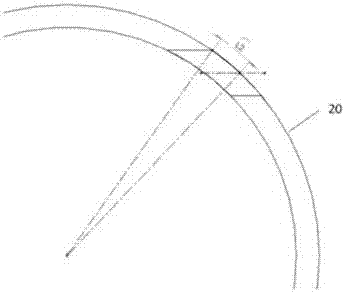
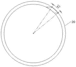
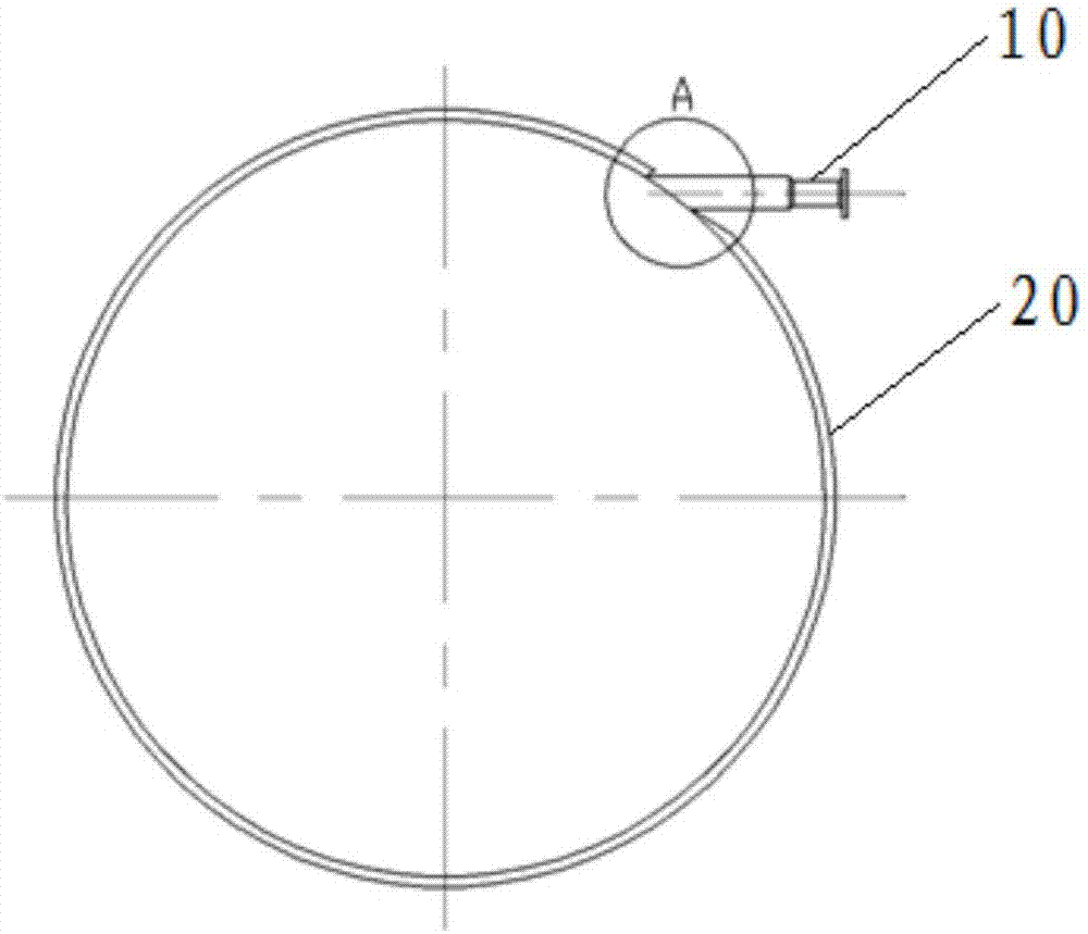
[0061] The present invention provides a pressure vessel with a non-concentric nozzle 10, wherein, in a preferred embodiment, the connection relationship between the non-concentric nozzle 10 and the pressure vessel cylinder 20 is as follows figure 1 As shown, it is preferable that the non-centripetal connection pipe 10 is welded to the barrel 20; and, as figure 2 As shown, in the welding operat...


PUM


Abstract

The invention discloses a pressure vessel. The pressure vessel is provided with a non-centripetal connecting pipe (10), wherein the non-centripetal connecting pipe (10) is connected to a tube body (20) of the pressure vessel in a non-centripetal manner, and connected with the tube body (20) through a groove; the groove is formed in the tube body (20); the tube body (20) and the non-centripetal connecting pipe (10) are welded through the groove; the groove is a single-edge V-shaped groove; and preferably, the distance from the upper endpoint of the groove, on the outer side of the tube body, to the connecting pipe is equal to the distance from the lower endpoint of the groove, on the outer side of the tube body, to the connecting pipe. According to the pressure vessel disclosed by the invention, the groove is formed, so that accuracy after gas cutting can be effectively guaranteed; and the root of the groove is not damaged, so that welding deformation can be effectively controlled, and the size of the welded connecting pipe can be guaranteed.

Description

Technical field [0001] The invention relates to a pressure vessel, in particular to a pressure vessel with a non-centripetal nozzle. Background technique [0002] Non-centripetal connection pipe is a common structural form in pressure vessel products. For the welding groove between the pipe and the cylinder, the conventional welding groove is processed with the non-centripetal connection pipe and the cylinder. The bevel at the acute angle has too much space in at least 1 / 4 of the circumference, which leads to a large increase in the amount of weld deposit metal filling during the welding process; while on the other side symmetrical to it, the weld deposit metal fills less, causing There is a huge difference in heat input during welding on both sides of the nozzle, and this phenomenon increases as the distance between the nozzle and the axial center of the cylinder increases. Therefore, such a groove form causes the following two serious problems after the welding of the non-cent...

Claims


Application Information

Patent Timeline
Patent Type & Authority Applications(China)
IPC IPC(8): B23K33/00F16J12/00
CPCF16J12/00B23K33/00Y02E30/30
Inventor 王磊杨明伟李洪利李学鸥张克路扬陶磊洁安旭
Owner HARBIN ELECTRIC CORP QINHUANGDAO HEAVY EQUIP
Features
  • R&D
  • Intellectual Property
  • Life Sciences
  • Materials
  • Tech Scout
  • Unparalleled Data Quality
  • Higher Quality Content
  • 60% Fewer Hallucinations
Learn More