Ceramic body grouting molding method

A ceramic body and grouting technology, applied in the field of ceramic manufacturing, can solve the problems of mold leakage, fast sizing speed, and the pipeline air is too late to be completely emptied, and achieves the effect of eliminating slurry leakage and reducing all emptying.

Active Publication Date: 2019-03-08
LIXIL AS SANITARY MFG (SHANGHAI) CO LTD
View PDF6 Cites 1 Cited by
  • Summary
  • Abstract
  • Description
  • Claims
  • Application Information

AI Technical Summary

Problems solved by technology

[0003] 1. The slurry is directly fed into the gypsum mold by the injection pump, and the slurry supply pressure is relatively high, resulting in serious slurry leakage of the mold and mud pollution on site;
[0004] 2. The slurry supply pressure is high, the sizing speed in the mold is fast, and the air in the pipeline and the mold cannot be completely emptied, resulting in defects, resulting in a thickness difference between the first green body and the last green body: 0.5-0.7mm

Method used


Image

  • Ceramic body grouting molding method
  • Ceramic body grouting molding method
  • Ceramic body grouting molding method

Examples


Embodiment Construction

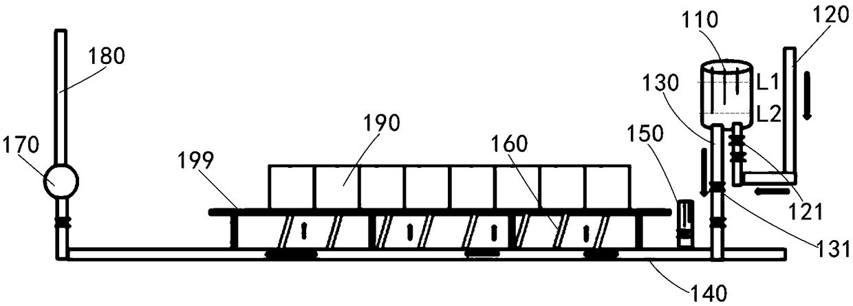
[0024] Such as Figure 1-3 Shown, a kind of ceramic green body grouting molding method comprises:

[0025] 1. Grouting: Open the grouting pipe 120, inject mud into the grouting barrel 110 connected to the atmosphere, until the mud in the grouting barrel 110 rises to the first liquid level L1, close the grouting pipe, and perform grouting .

[0026] 2. Grouting: Open the grouting pipe 130, inject the slurry into the grouting pipe 140 until the mud in the grouting barrel 110 drops to the second liquid level L2, close the grouting pipe 130, and return to the grouting step.

[0027] Three, mud injection molding preparation:

[0028] (1) During the pulping process, when the liquid level in the horizontal liquid level device 150 on the pulping pipe 140 reaches the preset liquid level, close the pulping pipe and perform step (2);

[0029] Wherein, the preset liquid level is flush with the liquid inlet of the mold 190 .

[0030] (2) After the liquid levels of the horizontal liquid...


PUM


Abstract

A grouting forming method for ceramic blanks comprises the steps of grouting, slurry blanking, slurry mold injection preparation and slurry mold injection forming. According to the grouting forming method for the ceramic blanks, the liquid level in a grouting barrel is controlled through a first liquid level and a second liquid level, the relatively constant grouting pressure can be kept in grouting and is small, slurry is prevented from leaking from seams of a mold, the effect that the same height (a preset liquid level) is kept when the slurry enters the mold is guaranteed through a horizontal liquid level device before slurry mold injection, it is ensured that air in a pipeline is completely exhausted, and the thickness difference between the blanks is reduced.

Description

technical field [0001] The invention relates to ceramic manufacturing technology, in particular to a method for slip-casting a ceramic green body. Background technique [0002] Ceramic products are usually formed by grouting. The traditional process is: the slurry adjusted by the raw material department is pumped into the mold by a plug pump through a pipeline, and the sizing height in the mold is controlled by the liquid level tube. After the slurry is formed in the plaster mold, The excess pulp in the mold is discharged into the pulp barrel through natural pulp discharge. The traditional process suffers from the following disadvantages: [0003] 1. The slurry is directly fed into the gypsum mold by the injection pump, and the slurry supply pressure is relatively high, resulting in serious slurry leakage of the mold and mud pollution on site; [0004] 2. The slurry supply pressure is high, the sizing speed in the mold is fast, and the air in the pipeline and the mold cann...

Claims


Application Information

Patent Timeline
Patent Type & Authority Patents(China)
IPC IPC(8): B28B1/26B28B13/02
CPCB28B1/26B28B13/0275
Inventor 毛法坚倪永林
Owner LIXIL AS SANITARY MFG (SHANGHAI) CO LTD
Why Eureka
Try Eureka