
Oil containment device

A technology of oil containment and hose, which is applied in the field of oil containment devices, can solve the problems of low oil containment efficiency, achieve high oil containment efficiency, reduce friction, and stabilize the movement of the ejector rod

Inactive Publication Date: 2017-06-23
ZHEJIANG OCEAN UNIV
View PDF8 Cites 5 Cited by
  • Summary
  • Abstract
  • Description
  • Claims
  • Application Information

AI Technical Summary

Problems solved by technology

The present invention realizes the oil confinement effect by means of the buoyancy of the rising bubbles and the planar potential flow generated by the rupture of the bubbles on the free liquid surface, and overcomes the shortcomings of the traditional oil containment boom during use, but the gas in the air curtain generation part only passes through the air pump Provided that due to the long exhaust pipe, the air pump needs to fill the exhaust pipe at the beginning of the air supply, which takes a long time, resulting in low oil containment efficiency

Method used


Image

  • Oil containment device
  • Oil containment device
  • Oil containment device

Examples


Embodiment Construction

[0023] The following are specific embodiments of the present invention and in conjunction with the accompanying drawings, the technical solutions of the present invention are further described, but the present invention is not limited to these embodiments.

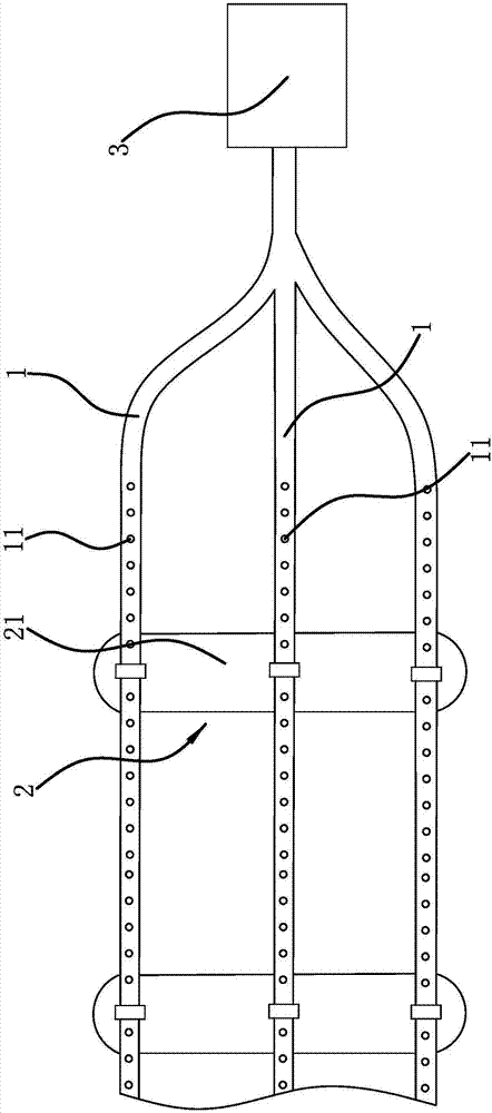
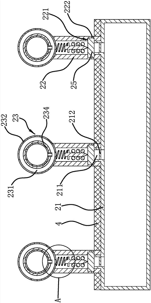
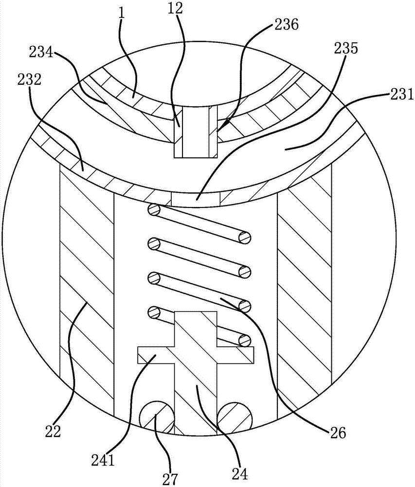
[0024] Such as figure 1 , figure 2 As shown, an oil containment device includes several exhaust hoses 1, which are arranged in the same direction and connected with the air pump 3. On the side wall of the exhaust hose 1, there are several Vent 11, the oil containment device also includes a number of fast charging devices 2, the fast charging device 2 includes a high-pressure gas tank 21 and a number of cylindrical installation shells 22, the high-pressure gas tank 21 has a number of gas outlets 211, and the gas outlets 211 pass through Metal film 212 covers, the lower ends of several installation shells 22 are all fixedly connected on the high-pressure gas tank 21, and the lower ends of several installation shells 22 are...


PUM


Abstract

The invention provides an oil containment device, and belongs to the technical field of offshore oil containment equipment. The oil containment device comprises a plurality of exhaust hoses and a plurality of quick charging devices. A plurality of exhaust holes are formed in the side walls of the exhaust hoses. Each quick charging device comprises a high-pressure air tank and a plurality of mounting shells. Each high-pressure air tank comprises a plurality of air outlets, wherein the air outlets are sealed by metal films. The lower ends of the mounting shells are fixedly connected to the high-pressure air tanks, connecting sleeves are fixedly connected to the upper ends of the mounting shells, and the exhaust hoses are arranged in the connecting sleeves in a penetrating mode. Ejector rods are arranged in the mounting shells in a sliding connection mode, water-soluble stop blocks are further fixedly connected with the interiors of the mounting shells, the ejector rods abut against the water-soluble stop blocks in a press mode under the action of springs, and when the water-soluble stop blocks dissolve, the ejector rods can penetrate through the metal films. The oil containment device can conduct quick oil containment and is higher in efficiency.

Description

technical field [0001] The invention belongs to the technical field of offshore oil containment equipment, and relates to an oil containment device. Background technique [0002] Crude oil leakage at sea is an important source of marine water pollution. When crude oil leaks, oil booms are needed to contain the oil. The oil booms are used to limit the oil layer to prevent the spread of crude oil and facilitate the removal of oil spills. However, the volume of the current oil boom increases. Large and inconvenient to use. [0003] In view of the above problems, the Chinese invention patent application (application number: 201310603497.1) discloses a device that uses air curtains to contain oil, including oil containment booms, air curtain generation parts and gas injection parts. The air curtain generation parts are arranged underwater. And it is connected with the gas injection part, and the oil containment boom surrounds the inner side and the outer side of the air curtain ...

Claims


Application Information

Patent Timeline
Patent Type & Authority Applications(China)
IPC IPC(8): E02B15/08
CPCE02B15/0864Y02A20/204
Inventor 王化明彭华超刘焕文万栋栋汪林峰许星磊
Owner ZHEJIANG OCEAN UNIV
Learn More