
Spading equipment used in wall surface

A kind of technology of equipment and remote control car, which is applied in the direction of building maintenance, construction, building construction, etc., which can solve the problems of physical burden, dust, increased harm to workers, rising labor costs, and incomplete removal of walls, etc., so as to reduce equipment maintenance costs, The effect of low investment, convenient water addition and discharge

Inactive Publication Date: 2017-06-23
DAXIN SCI & TECH INFORMATION RES INST
View PDF6 Cites 7 Cited by
  • Summary
  • Abstract
  • Description
  • Claims
  • Application Information

AI Technical Summary

Problems solved by technology

[0002] In order to experience life better and enjoy life, people begin to pursue individualized and artistic home decoration. In any case, decoration inevitably involves wall removal. When removing walls, due to the primitive tools, workers often rely on hand-held tools when removing walls. The shovel is used to eradicate the wall. It takes two people to work overtime for two days to eradicate the wall of only 80 square meters. Both manpower and cost are rising, and the efficiency is low. Excessive force will increase the physical burden of workers and the harm of dust to workers will also increase accordingly, which will cause workers to be tired of shoveling walls, and the landlord's home improvement costs will increase. Since the design elevation of commercial housing is 2900 mm, workers have to remove walls above 2000 mm. Sometimes it is necessary to take a ladder to shovel it, which makes it difficult for workers to clean up the high wall and cause part of the wall to be incompletely removed, which will affect the home decoration effect. Therefore, an efficient, convenient, and low-dust wall removal equipment needs to be developed.

Method used


Image

  • Spading equipment used in wall surface
  • Spading equipment used in wall surface
  • Spading equipment used in wall surface

Examples


Embodiment

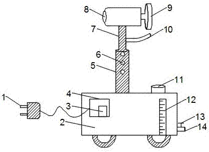
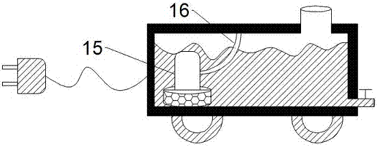
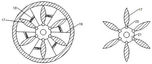
[0025] see figure 1 , figure 2 , image 3 ,and Figure 4 , the present invention provides a kind of equipment for eradicating walls, including a remote control car 2 and a remote control 22. Since the size of the remote control car 2 is 500*500*300 mm, and the hollow water tank is made of stainless steel, the remote control car 2 is added. Its own weight ensures the stability of the vehicle body. A power cord plug 1 is provided on the left side of the remote control car 2, and a control box 4 is connected to the right end of the power cord plug 1. The control box 4 is installed on the remote control car 2, and the control box 4 The interior of the remote control car 2 is provided with a single-chip microcomputer 3, and a water level gauge 12 is provided on the front of the remote control car 2. Because the water level gauge 12 can observe the water level situation inside the remote control car 2, to avoid the idling of the micro water pump 15, the water level gauge 12 is in...


PUM


Abstract

The invention discloses a device for eradicating walls, which comprises a remote control car and a remote control. A power cord plug is arranged on the left side of the remote control car, and a control box is connected to the right end of the power cord plug. The control box is installed On the remote control car, the inside of the control box is provided with a single-chip microcomputer, the front of the remote control car is provided with a water gauge, the upper surface of the remote control car is provided with a telescopic rod, and a pillar is installed in the telescopic rod, and The middle part is equipped with an atomizing nozzle, and the top of the pillar is equipped with a motor, and a cutting disc is installed on the motor, and a blade and a synchronous spring are installed on the cutting disc; the remote control is provided with a power button and a multi-dimensional Direction keys, because the setting of the atomizing nozzle can reduce the dust pollution in the cutting process, and the cutting disc set at the same time cooperates with the synchronous spring so that the vibration of the device is minimized when the wall is removed and the device works stably, so the invention works reliably and has low dust Ease of use is worth promoting.

Description

technical field [0001] The invention relates to the technical field of construction and home improvement, in particular to a device for removing walls. Background technique [0002] In order to experience life better and enjoy life, people begin to pursue individualized and artistic home decoration. In any case, decoration inevitably involves wall removal. When removing walls, due to the primitive tools, workers often rely on hand-held tools when removing walls. The shovel is used to eradicate the wall. It takes two people to work overtime for two days to eradicate the wall of only 80 square meters. Both manpower and cost are rising, and the efficiency is low. Excessive force will increase the physical burden of workers and the harm of dust to workers will also increase accordingly, which will cause workers to be tired of shoveling walls, and the landlord's home improvement costs will increase. Since the design elevation of commercial housing is 2900 mm, workers have to remo...

Claims


Application Information

Patent Timeline
Patent Type & Authority Applications(China)
IPC IPC(8): E04F21/00E04G23/00
CPCE04F21/00E04G23/00
Inventor 许焕明
Owner DAXIN SCI & TECH INFORMATION RES INST
Learn More