Fluid magnetic processor
A processor and fluid technology, applied in the fields of magnetic field/electric field water/sewage treatment, magnetic objects, through electric/magnetic refining, etc., can solve the problem of affecting the use effect, disappearing, the magnetization field of the permanent magnet cylinder and the gradient of the magnetic field are low, etc. Problems, to achieve the effect of improving the pass rate, reducing defects, and reducing the cost of electroplating process
- Summary
- Abstract
- Description
- Claims
- Application Information
AI Technical Summary
Problems solved by technology
Method used
Image
Examples
Embodiment 1
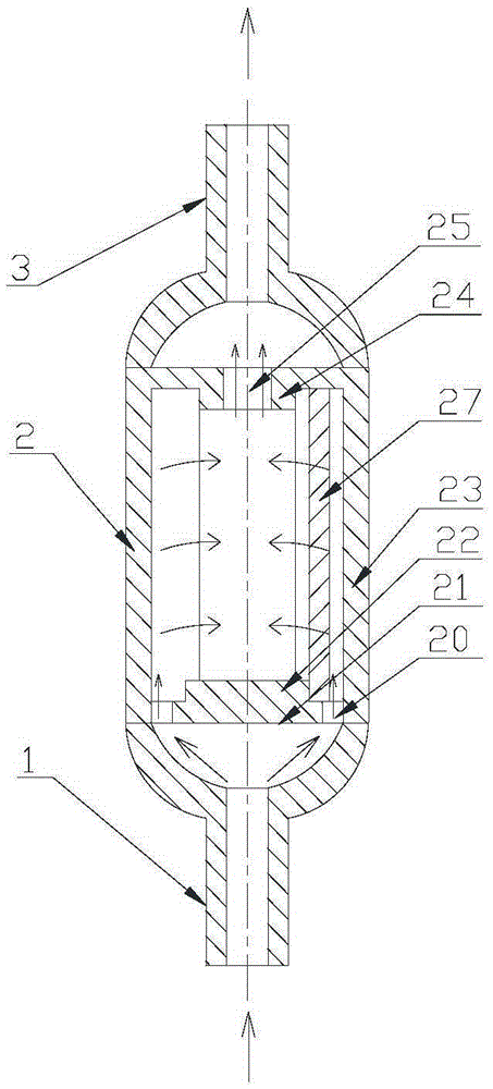
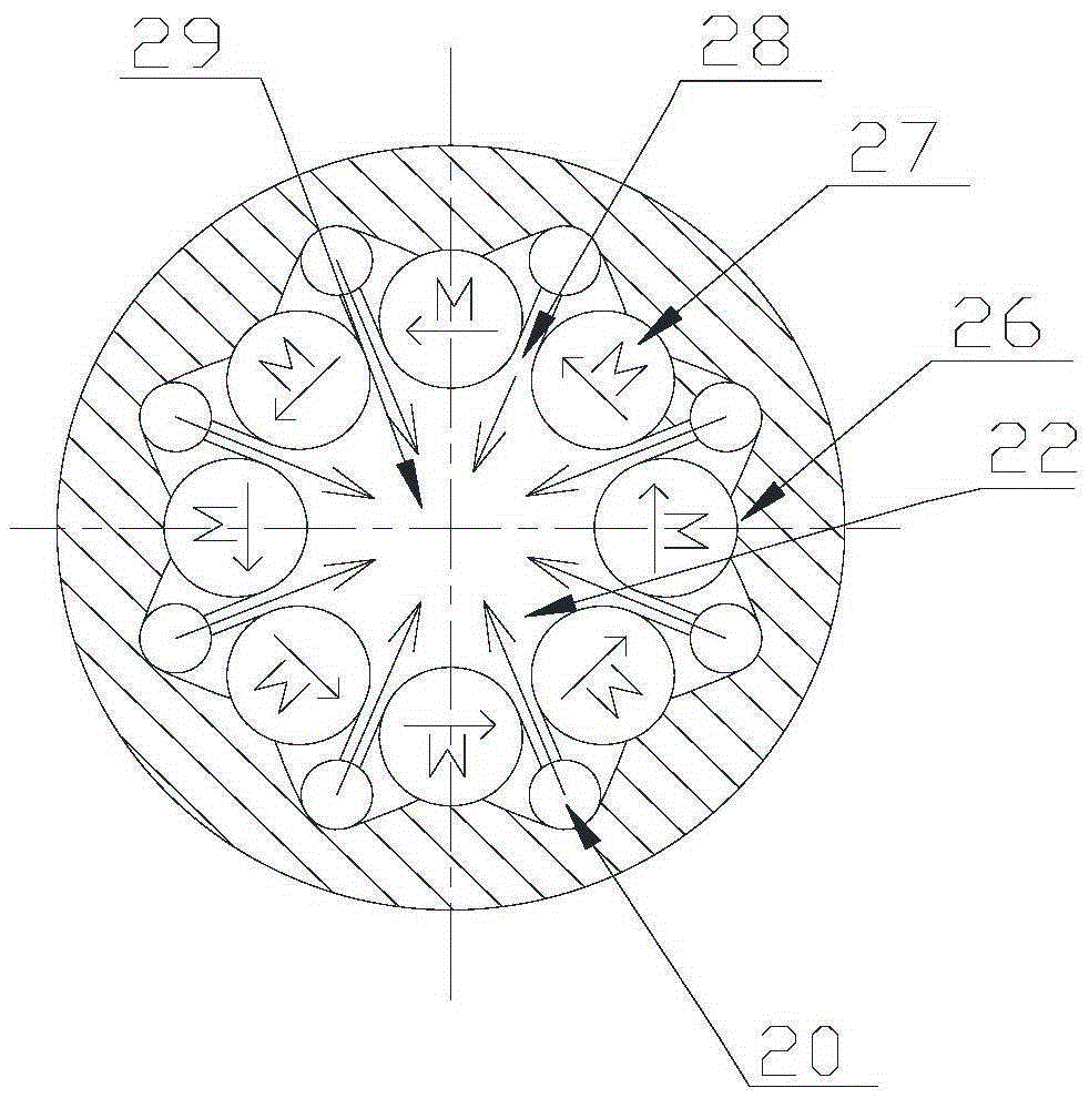
[0030] A kind of fluid magnetic processor, its structure is as figure 1 As shown, it consists of a body 2, and an inlet joint 1 and an outlet joint 3 connected to the upper and lower ends of the body 2. The body 2 is composed of a cover plate 21 , a housing 23 and a magnetic steel assembly 27 . The cover plate 21 has an inlet 20 connected to the inlet connector 1 and a permanent magnet source limiting structure 22 at the inlet end that fixes the magnetic steel assembly 27 . The housing 23 is provided with an outlet 25 connected to the outlet joint 3 and an outlet end permanent magnet source limiting structure 24 of a fixed magnetic steel assembly 27. The magnetic steel assembly 27 is arranged in the housing 23, and in the housing 23, a There is a permanent magnet source sealing structure 26, which is sleeved on the outside of the permanent magnet source.
[0031] The magnetic steel combination is composed of at least 5 permanent magnet sources connected end to end in the magn...
Embodiment 2
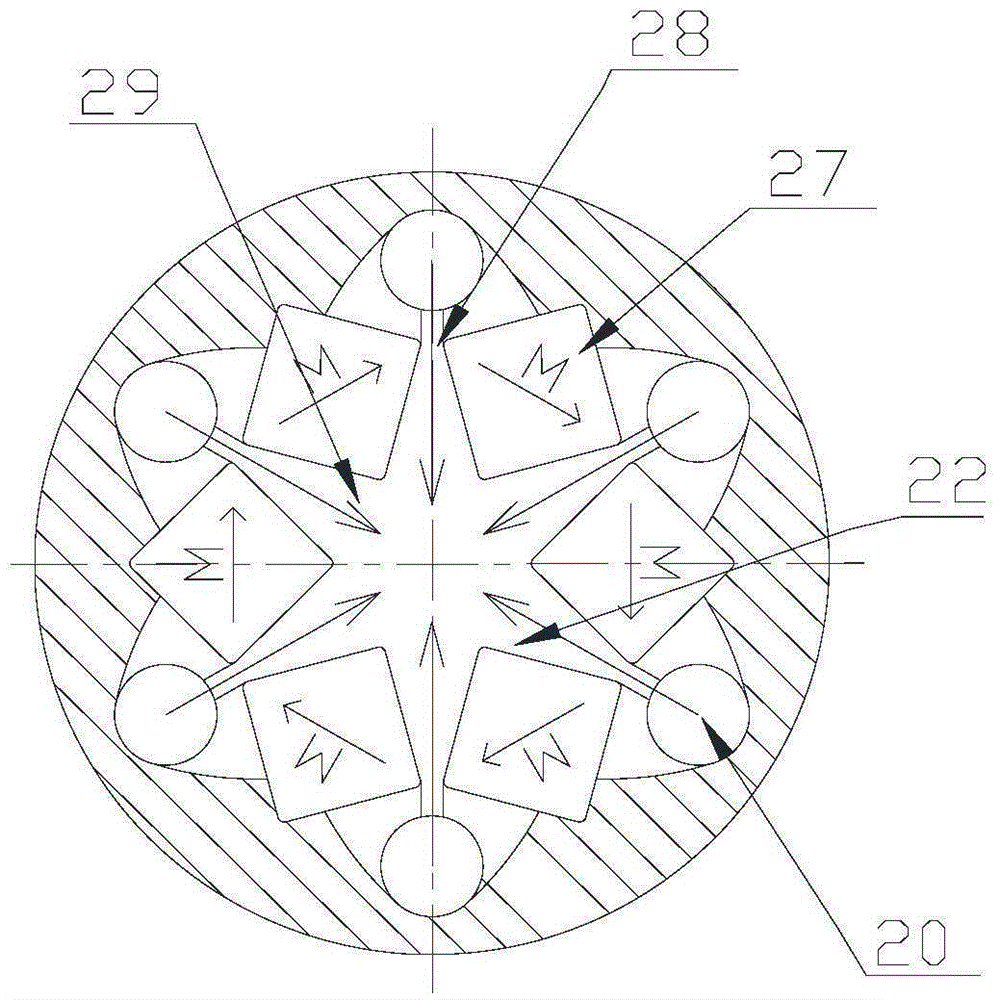
[0034] A kind of fluid magnetic processor, its structure is roughly the same as that of Embodiment 1, the difference is that this embodiment adopts a permanent magnet source with a square cross section (diagonal magnetization scheme), and the magnetic direction is clockwise to form a closed loop, as image 3 shown. In this way, the volume of the existing square-section permanent magnet source (parallel side magnetization scheme) is reduced by 20%, and the air gap magnetic field strength is increased by 25%. In this embodiment, the magnetic field strength can reach 1.63T.
[0035] Since the magnetic directions N and S of the permanent magnet source in the permanent magnet string are connected end to end, it has a strong cohesive force. Under the support of the permanent magnet source limiting structure 22 at the entrance end and the permanent magnet source limiting structure 24 at the outlet end, the permanent The magnetic string is strong enough to fix itself. The fluid outsi...
Embodiment 3
[0037] A kind of fluid magnetic processor, its structure is as Figure 4 As shown, it consists of a body 2 and an inlet joint 1 and an outlet joint 3 connected to the body 2 . The inlet joint 1 and the outlet joint 3 are compounded in a cylinder with the same diameter as the body 2, and are connected with the body 2 to form a whole. In this embodiment, the inlet joint 1 and the outlet joint 3 are located in the fluid magnetic processor. same end.
[0038]The body 2 is composed of a cover plate 21, a housing 23 and a magnetic steel assembly 27. The cover plate 21 has an inlet 20 connected to the inlet joint 1 and an outlet 25 connected to the outlet joint 3, and an inlet end of the fixed magnetic steel assembly 27. The permanent magnet source limiting structure, the permanent magnet source limiting structure 24 at the outlet end, and the magnetic steel combination 27 are arranged in the housing 23 .
[0039] The structure of the magnetic steel combination 27 is as follows F...
PUM
| Property | Measurement | Unit |
|---|---|---|
| Magnetic field strength | aaaaa | aaaaa |
| Magnetic field strength | aaaaa | aaaaa |
Abstract
Description
Claims
Application Information
 - R&D
- Intellectual Property
- Life Sciences
- Materials
- Tech Scout
- Unparalleled Data Quality
- Higher Quality Content
- 60% Fewer Hallucinations
Browse by: Latest US Patents, China's latest patents, Technical Efficacy Thesaurus, Application Domain, Technology Topic, Popular Technical Reports.
© 2025 PatSnap. All rights reserved.Legal|Privacy policy|Modern Slavery Act Transparency Statement|Sitemap|About US| Contact US: help@patsnap.com


