A Fluid Magnetic Processor

A processor and fluid technology, applied in the fields of magnetic field/electric field water/sewage treatment, magnetic objects, refining by electricity/magnetic, etc., can solve the problem of affecting the use effect, the magnetization field of the permanent magnet cylinder and the magnetic field gradient are low, disappear, etc. problems, to achieve the effect of improving the pass rate, reducing the cost of the electroplating process, and reducing the defects

Active Publication Date: 2019-07-05
SHANGHAI JIELING MAGNETIC MATERIAL & DEVICES
View PDF9 Cites 0 Cited by
  • Summary
  • Abstract
  • Description
  • Claims
  • Application Information

AI Technical Summary

Problems solved by technology

However, the permanent magnet cylinder used in this device still has the problem of low magnetization field and magnetic field gradient, which leads to obvious functions of the product at room temperature. Once the ambient temperature rises, the function gradually declines or even disappears, which seriously affects the use effect. Therefore Need to redesign the magnetic circuit

Method used


Image

  • A Fluid Magnetic Processor
  • A Fluid Magnetic Processor
  • A Fluid Magnetic Processor

Examples


Embodiment 1

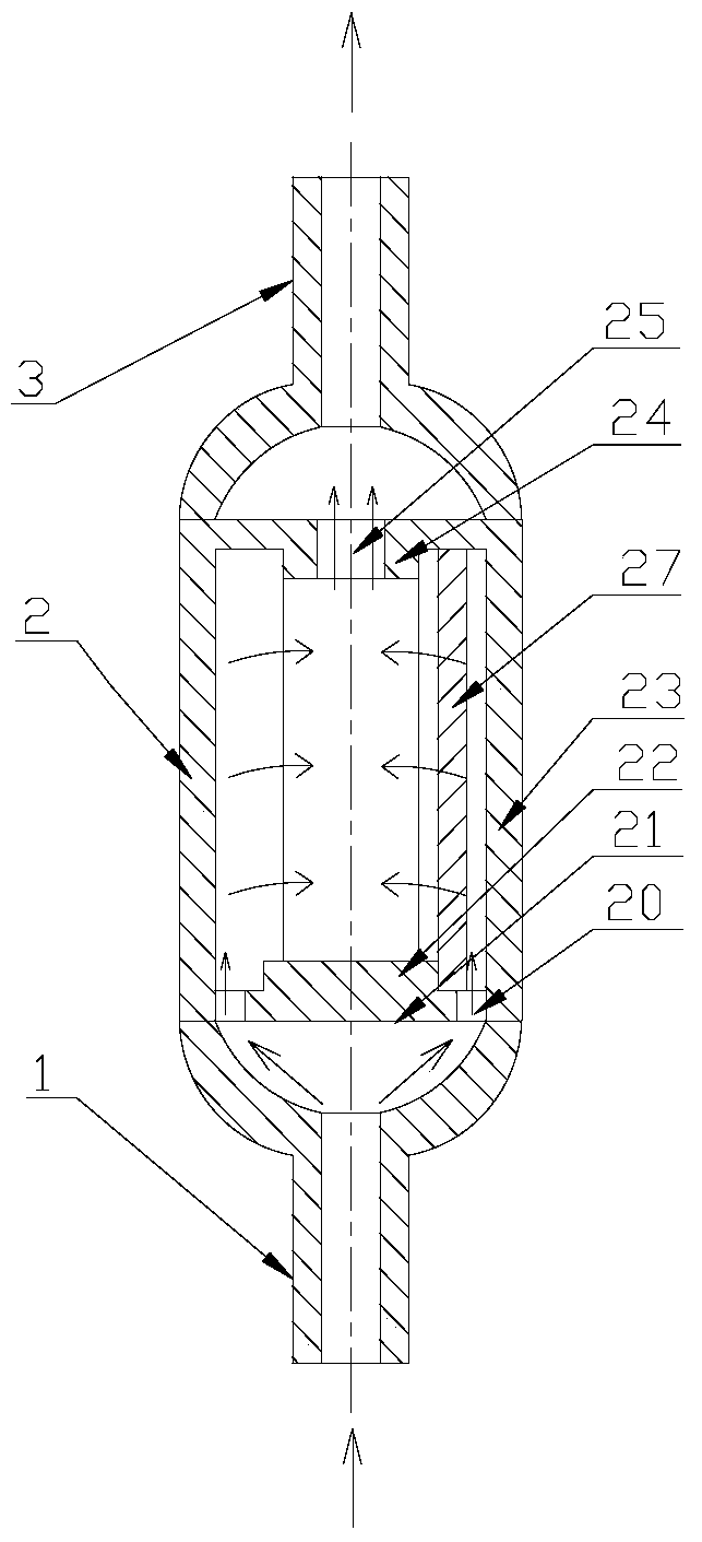
[0030] A kind of fluid magnetic processor, its structure is as figure 1 As shown, it consists of a body 2, and an inlet joint 1 and an outlet joint 3 connected to the upper and lower ends of the body 2. The body 2 is composed of a cover plate 21 , a housing 23 and a magnetic steel assembly 27 . The cover plate 21 has an inlet 20 connected to the inlet connector 1 and a permanent magnet source limiting structure 22 at the inlet end that fixes the magnetic steel assembly 27 . The housing 23 is provided with an outlet 25 connected to the outlet joint 3 and an outlet end permanent magnet source limiting structure 24 of a fixed magnetic steel assembly 27. The magnetic steel assembly 27 is arranged in the housing 23, and in the housing 23, a There is a permanent magnet source sealing structure 26, which is sleeved on the outside of the permanent magnet source.

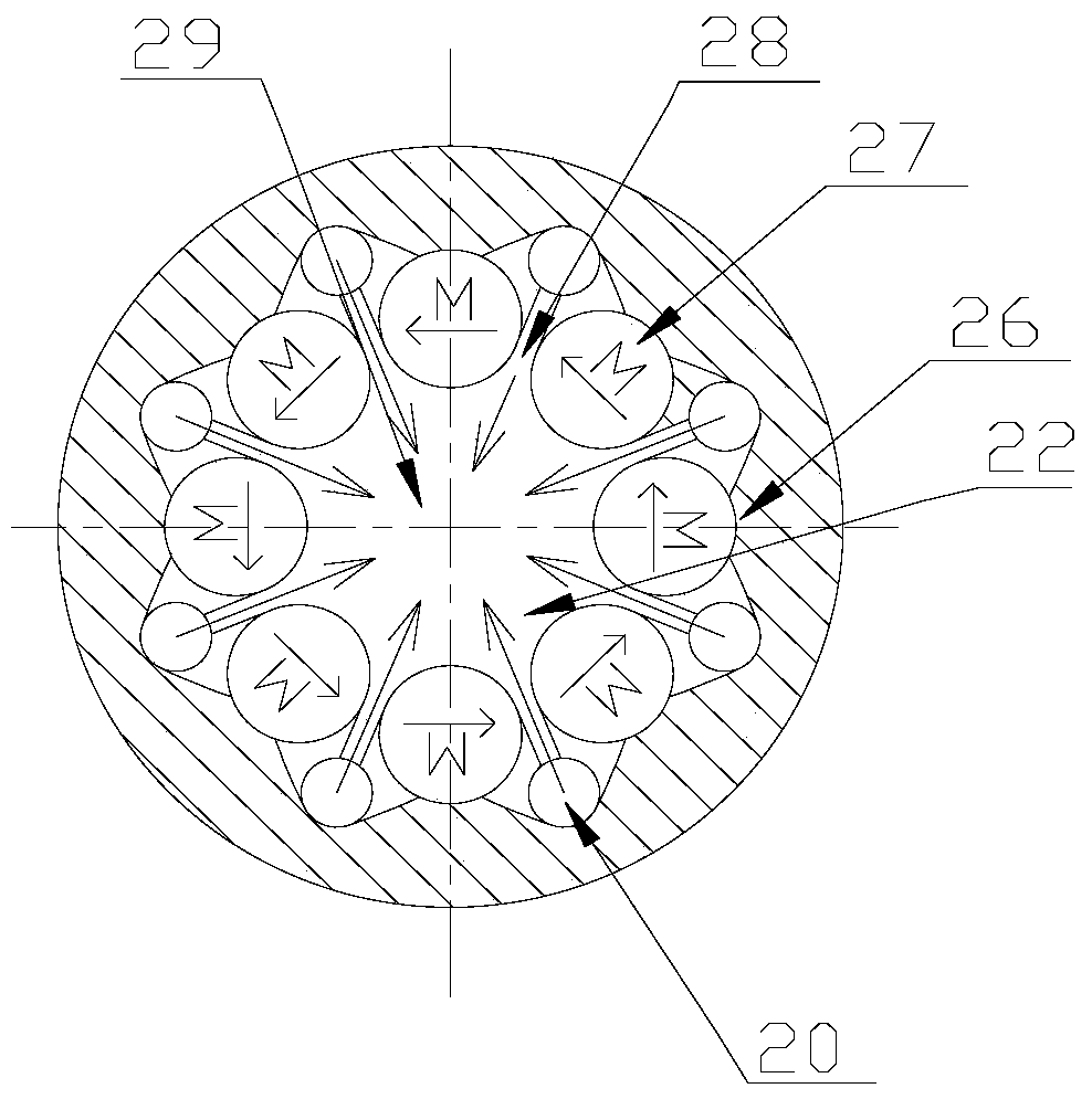
[0031] The magnetic steel combination is composed of at least 5 permanent magnet sources connected end to end in the magn...

Embodiment 2

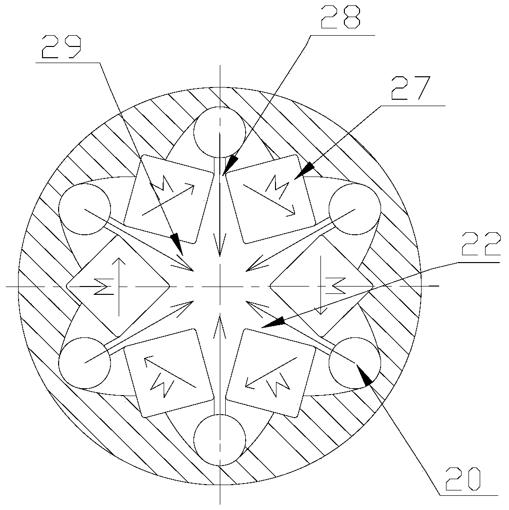
[0034] A kind of fluid magnetic processor, its structure is roughly the same as that of Embodiment 1, the difference is that this embodiment adopts a permanent magnet source with a square cross section (diagonal magnetization scheme), and the magnetic direction is clockwise to form a closed loop, as image 3 shown. In this way, the volume of the existing square-section permanent magnet source (parallel side magnetization scheme) is reduced by 20%, and the air gap magnetic field strength is increased by 25%. In this embodiment, the magnetic field strength can reach 1.63T.

[0035] Since the magnetic directions N and S of the permanent magnet source in the permanent magnet string are connected end to end, it has a strong cohesive force. Under the support of the permanent magnet source limiting structure 22 at the entrance end and the permanent magnet source limiting structure 24 at the outlet end, the permanent The magnetic string is strong enough to fix itself. The fluid outsi...

Embodiment 3

[0037] A kind of fluid magnetic processor, its structure is as Figure 4 As shown, it consists of a body 2 and an inlet joint 1 and an outlet joint 3 connected to the body 2 . The inlet joint 1 and the outlet joint 3 are compounded in a cylinder with the same diameter as the body 2, and are connected with the body 2 to form a whole. In this embodiment, the inlet joint 1 and the outlet joint 3 are located in the fluid magnetic processor. same end.

[0038]The body 2 is composed of a cover plate 21, a housing 23 and a magnetic steel assembly 27. The cover plate 21 has an inlet 20 connected to the inlet joint 1 and an outlet 25 connected to the outlet joint 3, and an inlet end of the fixed magnetic steel assembly 27. The permanent magnet source limiting structure, the permanent magnet source limiting structure 24 at the outlet end, and the magnetic steel combination 27 are arranged in the housing 23 .

[0039] The structure of the magnetic steel combination 27 is as follows F...


PUM


Abstract

The invention relates to a fluid magnetic processor. The fluid magnetic processor is composed of a body (2), an inlet joint (1) and an outlet joint (3). The inlet joint (1) and the outlet joint (3) are connected to the body (2). The body (2) is composed of a cover plate (21), a housing (23) and a magnetic steel combination (27). The magnetic steel combination (27) is a permanent magnet string enclosed by end-to-end connection of multiple permanent magnet sources along a magnetism direction from N poles to S poles. An air gap is kept between adjacent permanent magnet sources. The permanent magnet sources are different from the vertical sectional area of the magnetism direction in terms of the area. As for the permanent magnet sources, the middle areas are the biggest with areas close to air gaps gradually becoming smaller. Compared with the prior art, the fluid magnetic processor has the following beneficial effects: high magnetic field intensity and high magnetic field gradient for the working air gaps are realized.

Description

technical field [0001] The invention relates to a magnetizing device, in particular to a fluid magnetic processor. Background technique [0002] Existing practical devices require that the edge of the magnet should not have chamfers or be as small as possible, which does not meet the general process of magnet electroplating. Not only is it difficult to process, it is difficult to guarantee, magnet damage and defects are difficult to avoid, and the quality of electroplating is also difficult to guarantee. [0003] Chinese patent CN103821639A discloses a fuel activation device. There is an oil inlet joint on the first end cover at one end of the housing, and an oil outlet joint on the second end cover at the other end; the upper end of the permanent magnet cylinder in the housing is provided with a sealing ring, and the lower end is provided with a sealing plate; The jet tube is located in the oil flow area, and there are several jet holes at the inner end of the jet tube; th...

Claims


Application Information

Patent Timeline
Patent Type & Authority Patents(China)
IPC IPC(8): H01F13/00C02F1/48C10G32/02
Inventor 张慧欣张诗渊
Owner SHANGHAI JIELING MAGNETIC MATERIAL & DEVICES
Why Eureka
Try Eureka