
A prefabricated assembled reinforced concrete frame structure support and reinforcement node member

A reinforced concrete and frame structure technology, applied in building construction, construction, building maintenance, etc., can solve the problems of stress concentration in the core area of ​​frame beam-column joints, complicated construction of joint outer steel, long construction period, etc., and save construction time. and cost, avoid adverse effects, purchase and process the effect of convenience

Active Publication Date: 2019-02-19
HARBIN INST OF TECH
View PDF5 Cites 2 Cited by
  • Summary
  • Abstract
  • Description
  • Claims
  • Application Information

AI Technical Summary

Problems solved by technology

[0007] The purpose of the present invention is to solve the existing problems that the construction period is long and the joints are easily damaged when the reinforced concrete frame structure is reinforced by using supports. At the same time, the post-anchoring technology of the existing reinforced joints is likely to cause stress concentration in the core area of ​​the frame beam-column joints and The construction of node outsourcing steel is complicated and the construction period is long

Method used


Image

  • A prefabricated assembled reinforced concrete frame structure support and reinforcement node member
  • A prefabricated assembled reinforced concrete frame structure support and reinforcement node member
  • A prefabricated assembled reinforced concrete frame structure support and reinforcement node member

Examples


specific Embodiment approach 1

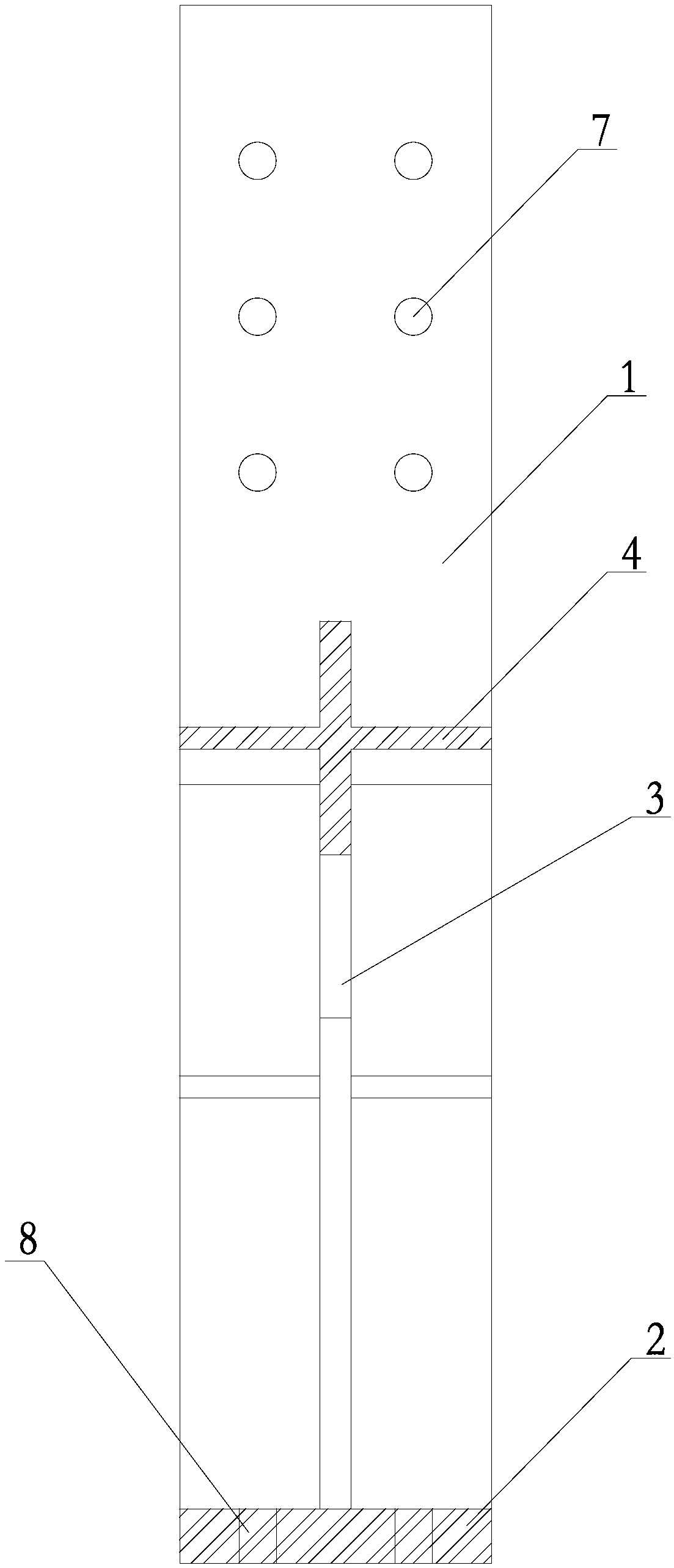
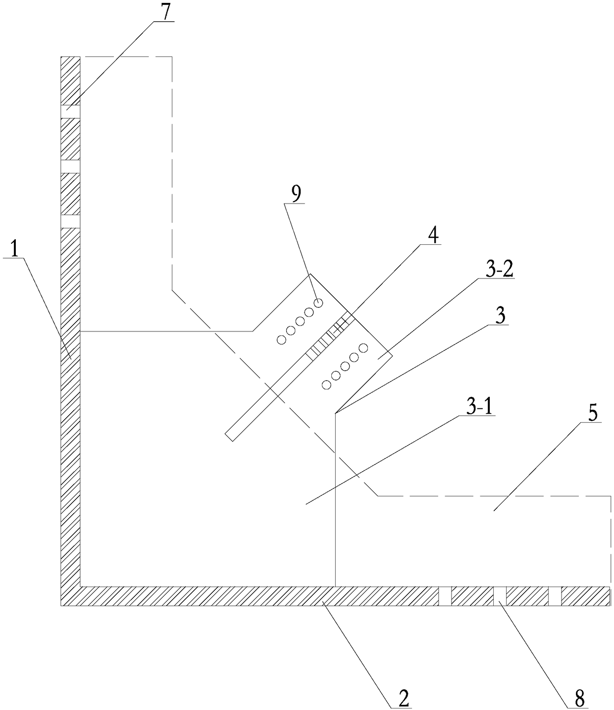
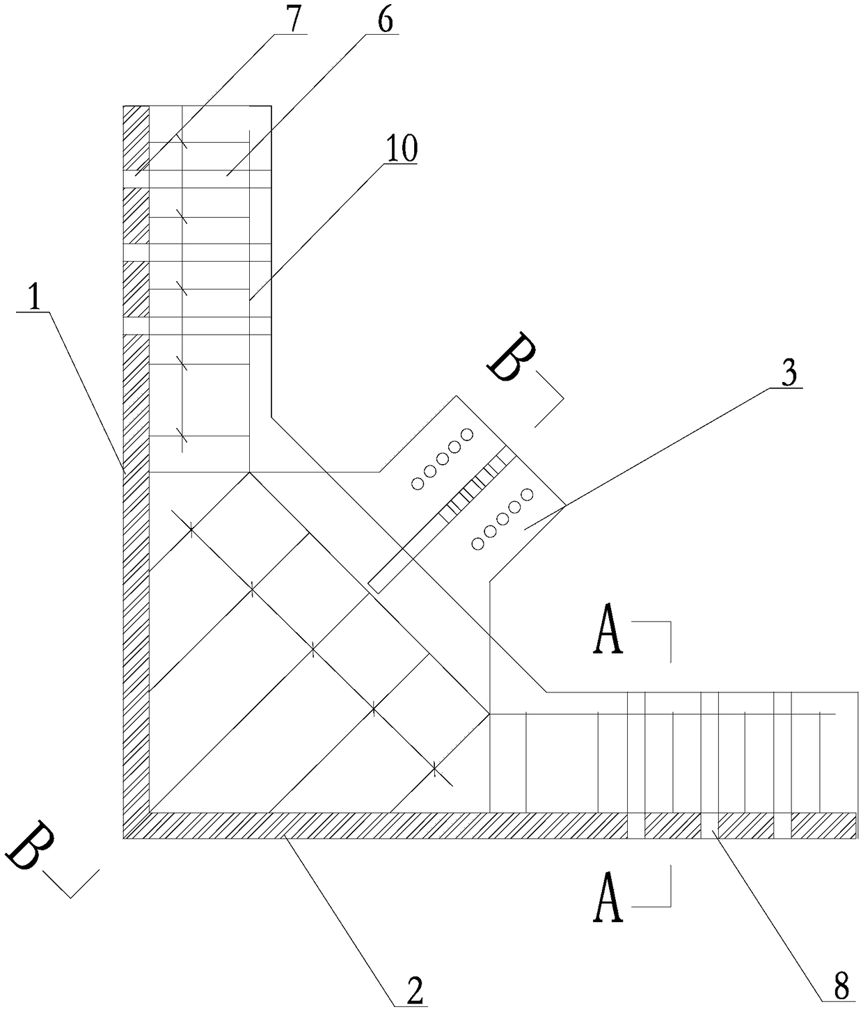
[0020] Specific implementation mode one: combine Figure 1 to Figure 8 Describe this embodiment, this embodiment includes first steel plate 1, second steel plate 2, support gusset plate 3, gusset plate stiffener 4, concrete 5, multiple pre-embedded steel pipes 6, multiple reinforcing longitudinal bars 10, multiple first A reinforcing stirrup 11 and a plurality of second reinforcing stirrups 12, the first steel plate 1 is vertically welded to one end of the second steel plate 2 arranged horizontally, a plurality of first reserved holes 7 are opened on the top of the first steel plate 1, and the first steel plate 1 The other end of the second steel plate 2 is provided with a plurality of second reserved holes 8, and a pre-embedded steel pipe 6 is respectively inserted and welded in each first reserved hole 7 and each second reserved hole 8 for realizing node components Bolt connection with the beam column, the inner diameter of the pre-embedded steel pipe 6 is the same as the di...

specific Embodiment approach 2

[0025] Specific implementation mode two: combination Figure 3 to Figure 8Describe this embodiment, a plurality of first reinforcing stirrups 11 of this embodiment are welded on the first steel plate 1 and the second steel plate 2, and one end of a plurality of second reinforcing stirrups 12 is welded on the first steel plate 1 and the second steel plate 2, the other ends of multiple second reinforcing stirrups 12 are welded on the supporting gusset plate 3, and multiple reinforcing longitudinal bars 10 pass through and are tied to multiple first reinforcing stirrups 11 and multiple second reinforcing stirrups 12 superior. With such arrangement, it is convenient to provide frame support for the poured concrete, meanwhile, the strength of the joint is increased and the service life is long. Other compositions and connections are the same as in the first embodiment.

specific Embodiment approach 3

[0026] Specific implementation mode three: combination Figure 6 To illustrate this embodiment, the reinforced longitudinal bar 10 of this embodiment includes a vertical section steel bar 10-1, an inclined section steel bar 10-2 and a horizontal section steel bar 10-3, a vertical section steel bar 10-1, and an inclined section steel bar 10-2 The steel bar 10-3 in the horizontal section is sequentially fixed and integrated, and the prefabricated steel bar 10 is formed by a steel bar bending machine. Such setting facilitates matching with the structure of the node components to be prefabricated. Other compositions and connections are the same as those in Embodiment 1 or Embodiment 2.


PUM


Abstract

The invention discloses a supporting and strengthening joint member of a prefabricated assembly type reinforced concrete frame structure and relates to a supporting and strengthening joint member. According to the supporting and strengthening joint member of the prefabricated assembly type reinforced concrete frame structure, the problem that when a reinforced concrete frame structure is strengthened through supports, the construction period is long, and a joint is easy to damage is solved. A first steel plate is vertically welded at one end of a horizontally-arranged second steel plate. A supporting joint plate is welded on the first steel plate and the second steel plate. A joint plate stiffening rib is perpendicularly mounted on the supporting joint plate. Strengthened rebars are mounted on the supporting joint plate. A steel formwork covers an area formed by enclosing of the first steel plate, the second steel plate and the supporting joint plate. A plurality of pre-embedded steel pipes are perpendicularly welded to first preformed holes and second preformed holes correspondingly. Concrete is poured in the area formed by enclosing of the first steel plate, the second steel plate and the supporting joint plate. The supporting and strengthening joint member is used for the construction industry.

Description

technical field [0001] The present invention relates to a prefabricated assembled node component, in particular, it is a prefabricated assembled node component used when using inter-column supports to reinforce existing reinforced concrete frame structures, and is mainly used for single inclined bar type center support reinforcement, Connection nodes for cruciform cross bracing reinforcement, herringbone and V-shaped center bracing reinforcement (including anti-buckling bracing reinforcement). Background technique [0002] The simple frame structure system has low lateral stiffness, and a double lateral force system can be formed by setting steel braces between the frame structure columns to reinforce it. Studies have shown that the reinforced concrete frame structure can significantly improve the ability to resist earthquakes and wind loads. In particular, the use of buckling-resistant bracing (BRB) will significantly improve the energy dissipation capacity of the structure...

Claims


Application Information

Patent Timeline
Patent Type & Authority Patents(China)
IPC IPC(8): E04G23/02E04B1/21
CPCE04B1/21E04B1/215E04G23/0218
Inventor 曾聪
Owner HARBIN INST OF TECH
Learn More