
High-precision low-cost electronic measurement system

An electronic measurement, low-cost technology, applied in the direction of measuring devices, instruments, etc., can solve the problems of difficult popularization and popularization of high-precision electronic measurement systems, measurement accuracy, cost, volume and other parameter limitations, and achieve the goal of simplifying development difficulty and reducing costs Effect

Inactive Publication Date: 2017-06-27
HANGZHOU RUIXUN WEIXIN TECH CO LTD
View PDF3 Cites 2 Cited by
  • Summary
  • Abstract
  • Description
  • Claims
  • Application Information

AI Technical Summary

Problems solved by technology

[0010] The purpose of the present invention is to provide a high-precision and low-cost electronic measurement system to solve the problem that the measurement accuracy, cost, volume and other parameters of traditional electronic precision measurement equipment are mutually restricted, making it difficult to popularize the high-precision electronic measurement system.

Method used


Image

  • High-precision low-cost electronic measurement system

Examples


Embodiment Construction

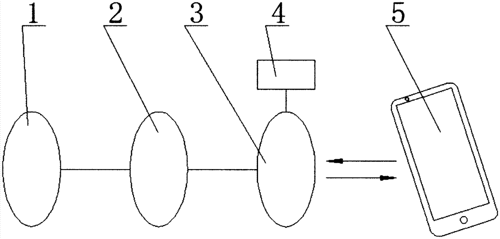
[0019] like figure 1 As shown, the sensor module 1 transmits the electrical signals measured by one or more sensors to the basic signal conditioning circuit 2 during measurement. After the basic signal conditioning circuit 2 performs basic amplification and conversion on the signal of the sensor module 1, the signal is sent to the basic data processing and communication module 3 for further sampling and preparation for transmission. At this time, the reason for simplifying and reducing the signal conditioning work of the basic signal conditioning circuit 2 as much as possible is because any sensor signal conditioning circuit will inevitably carry its own burden when it completes the amplification, shaping or conversion of the signal, or the main goal of filtering out specific noise. This is essentially to increase the number of variables in the system error in subsequent software operations. In addition to increasing hardware costs, it is also unfavorable for subsequent signa...


PUM


Abstract

The invention discloses a high-precision and low-cost electronic measuring system, which belongs to the field of electronic measuring instruments. The present invention transfers as much measurement signal conditioning work as possible from the hardware circuit to the software calculation on the intelligent mobile device, and calls the built-in feature code of the system by the software, the interpolation data table of the system itself or the error elimination formula and its calculation parameters and other methods to improve measurement accuracy and reduce system cost. The invention solves the contradiction that the existing electronic measurement system cannot take into account the three aspects of cost, volume and measurement accuracy, and can be used to manufacture independent high-precision electronic measurement instruments, and can also be used for high-performance measurement modules in various equipment.

Description

technical field [0001] The invention relates to an electronic measurement system that improves accuracy and reduces cost by transferring as much measurement signal conditioning work as possible from hardware circuits to software calculations on smart mobile devices. Background technique [0002] As we all know, the ratio of the output value of the sensor to the input value is not a straight line. Therefore, it is often necessary to determine the static linearity of the sensor by comparing the actual output value with the fitted straight line. In addition, sensors need calibration data to ensure accuracy. However, due to cost and production efficiency constraints, it is difficult for the sensor to accurately measure its own characteristic curve during the production process. It can only be calibrated with the general data of all products under the premise of ensuring that the accuracy of the same batch of sensors is within the required range. The accuracy of individual sens...

Claims


Application Information

Patent Timeline
Patent Type & Authority Applications(China)
IPC IPC(8): G01D21/00G01D21/02
CPCG01D21/00G01D21/02
Inventor 赵文扬李影
Owner HANGZHOU RUIXUN WEIXIN TECH CO LTD
Learn More