Motor stalling testing device

A test device and motor stalling technology, applied in the automotive field, to achieve the effect of increasing test functions and facilitating installation

Active Publication Date: 2017-06-27
BEIQI FOTON MOTOR CO LTD
View PDF8 Cites 12 Cited by
  • Summary
  • Abstract
  • Description
  • Claims
  • Application Information

AI Technical Summary

Problems solved by technology

[0004] The main purpose of the present invention is to provide a motor stall test device to solve the pro

Method used


Image

  • Motor stalling testing device
  • Motor stalling testing device

Examples


Embodiment Construction

[0021] It should be noted that, in the case of no conflict, the embodiments in the present application and the features in the embodiments can be combined with each other. The present invention will be described in detail below with reference to the accompanying drawings and examples.

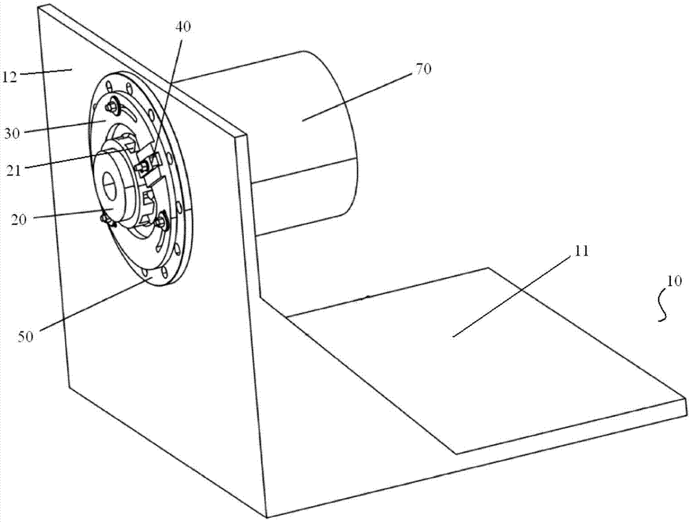
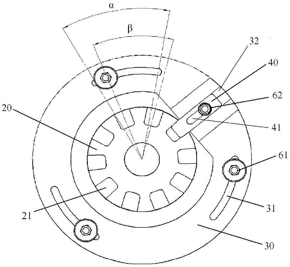
[0022] Such as figure 1 and figure 2 As shown, the motor stall test device of this embodiment includes a test frame 10 , a rotating disk 20 , a positioning part 30 and a locking part 40 . The rotating disk 20 is sleeved on the output shaft of the motor 70 to be tested, and the rotating disk 20 rotates with the output shaft of the motor 70 to be tested. The rotating disk 20 is provided with a plurality of fixing grooves 21 along its circumference, and the locking part 40 has a locking position and an unlocking position. position, the positioning part 30 is rotatably arranged on the test frame 10, the positioning part 30 is sleeved outside the rotating disk 20 and coaxially arranged with the r...


PUM


Abstract

The invention provides a motor stalling testing device, which comprises a testing frame (10), a rotating disc (20), a locking part (40) and a positioning part (30), wherein the rotating disc (20) sleeves the output shaft of a to-be-tested motor (70), the rotating disc (20) rotates along with the output shaft of the to-be-tested motor (70), and the rotating disc (20) is provided with multiple fixing grooves (21) along the circumference; the locking part (40) is provided with a locking position and an unlocking position; the positioning part (30) is arranged on the testing frame (10) in a rotatable mode, the positioning part (30) sleeves the rotating disc (20) and is arranged coaxially with the rotating disc (20), the locking part (40) is arranged on the positioning part (30), and the different positions of the positioning part (30) on the testing frame (10) are adjusted to carry out stalling test on the multiple positions of the to-be-tested motor (70). The technical scheme of the invention can effectively solve the problem that stalling measurement can only be carried out on one position of the rotation shaft of the motor in the prior art.

Description

technical field [0001] The invention relates to the technical field of automobiles, in particular to a testing device for motor stalling. Background technique [0002] At present, motors and controllers for new energy vehicles need to be stalled in the process of testing, research and development, and debugging to test information such as performance parameters of the motors and controllers. [0003] In the prior art, the stalling method of the motor and the controller generally adopts a fixed-angle stalling test method, that is, a rotating disk with fixed slots is installed on the output shaft of the motor, and then the locking pin on the bracket and the adapter The fixing holes on the disc cooperate to realize the function of blocking the motor, and the bracket is provided with a sliding groove, and the locking pin is installed in the sliding groove. When in use, it will be affected by the distribution of the fixed hole positions on the rotating disk, and the stall measur...

Claims


Application Information

Patent Timeline
IPC IPC(8): G01R31/34
CPCG01R31/34
Inventor 李艳波王晓辉杨卓王野石会军
Owner BEIQI FOTON MOTOR CO LTD
Why Eureka
Try Eureka