
Charging pile automatic detection system and method

An automatic detection and detection method technology, applied in the direction of measuring electricity, measuring devices, measuring electrical variables, etc., can solve the problems of increasing detection cost, troublesome operation, prolonging detection time, etc., to achieve accurate measurement, realize response time, and improve detection efficiency effect

Pending Publication Date: 2020-11-27
SHANDONG LUNENG SOFTWARE TECH
View PDF12 Cites 3 Cited by
  • Summary
  • Abstract
  • Description
  • Claims
  • Application Information

AI Technical Summary

Problems solved by technology

The inventors found that the testing items require high technical level and rich work experience of the testing personnel. During the maintenance process, the testing personnel are required to conduct fault analysis, and the positioning of the problems caused by the charging pile requires repeated attempts, which prolongs the detection time and increases test cost
Moreover, the detection needs to carry external equipment such as oscilloscope, wave recorder, etc., which is troublesome to operate

Method used


Image

  • Charging pile automatic detection system and method
  • Charging pile automatic detection system and method
  • Charging pile automatic detection system and method

Examples


Embodiment Construction

[0041] The present invention will be further described below in conjunction with the accompanying drawings and embodiments.

[0042] It should be noted that the following detailed description is exemplary and intended to provide further explanation of the present invention. Unless defined otherwise, all technical and scientific terms used herein have the same meaning as commonly understood by one of ordinary skill in the art to which this invention belongs.

[0043] It should be noted that the terminology used here is only for describing specific embodiments, and is not intended to limit exemplary embodiments according to the present invention. As used herein, unless the context clearly dictates otherwise, the singular is intended to include the plural, and it should also be understood that when the terms "comprising" and / or "comprising" are used in this specification, they mean There are features, steps, operations, means, components and / or combinations thereof.

[0044] re...


PUM


Abstract

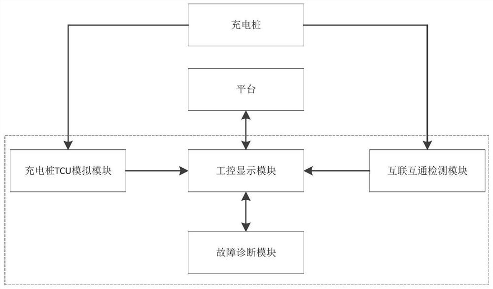
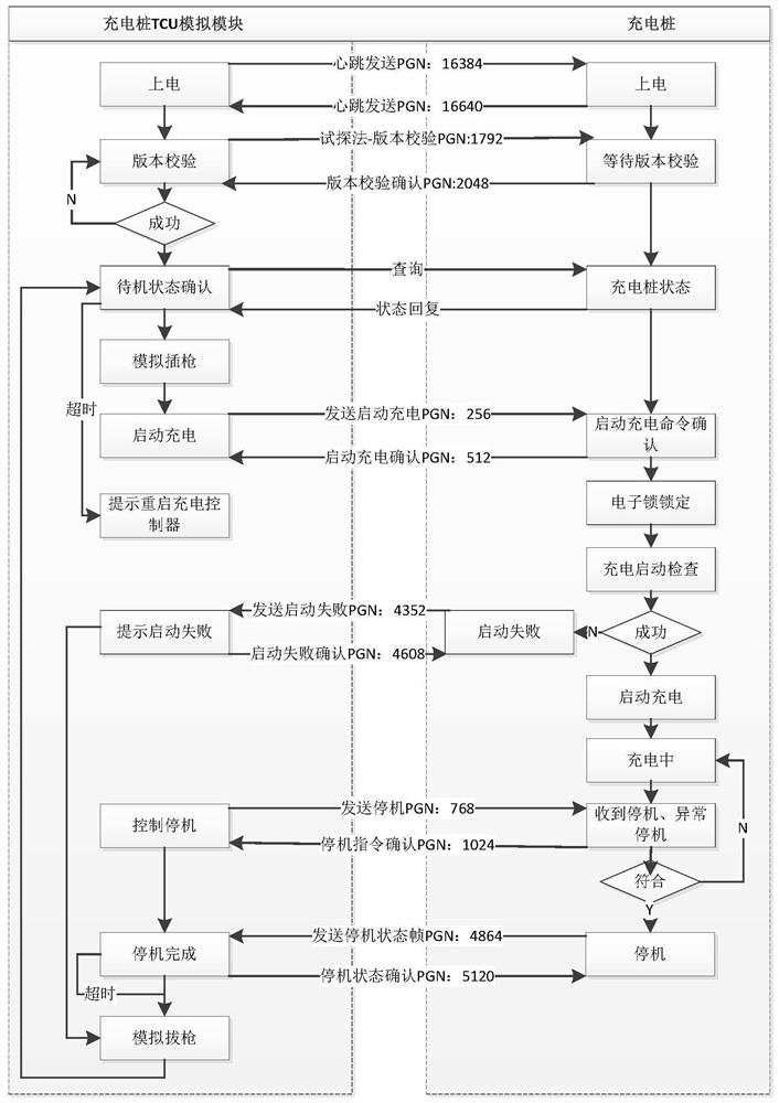
The invention provides a charging pile automatic detection system and method. The charging pile automatic detection system comprises a charging pile TCU simulation module, an interconnection and intercommunication detection module, an industrial control display module and a fault diagnosis module, wherein the charging pile TCU simulation module communicates with a charging pile and is used for simulating a TCU to automatically control the charging pile to start, stop and return to the initial charging state, collecting charging pile alarm and fault information and uploading the charging pile alarm and fault information to the industrial control display module; the interconnection and intercommunication detection module is connected with the charging pile through a charging gun and is usedfor simulating an interoperation test project to test the charging pile; the industrial control display module is responsible for starting a detection process, displaying the detection process and stopping the detection process, receiving and automatically summarizing the charging pile alarm and fault information and the test result uploaded by the interconnection and intercommunication detectionmodule, and generating a currently detected database; and the fault diagnosis module is used for pushing a fault diagnosis scheme according to the currently detected database and guiding the detectionpersonnel to change corresponding components in the charging pile for repeated detection.

Description

technical field [0001] The invention belongs to the field of operation inspection of charging piles, and in particular relates to an automatic detection system and method for charging piles. Background technique [0002] The statements in this section merely provide background information related to the present invention and do not necessarily constitute prior art. [0003] At present, there are hundreds of sub-items in the State Grid operation and maintenance charging pile interconnection test project. During the detection process of each sub-item, the inspector or operation and maintenance personnel need to click on the charging pile screen to swipe the card to start the operation. The screen of the charging pile manually operated returns to the initial state. Frequent personnel operations prolong the detection time and require the cooperation of multiple detection personnel or operation and maintenance personnel. After the test is completed, it is necessary to manually ...

Claims


Application Information

Patent Timeline
Patent Type & Authority Applications(China)
IPC IPC(8): G01R31/00G06F16/2455
CPCG01R31/00G06F16/2455G06F16/24552Y02T90/16Y02T10/7072Y02T90/12Y02T10/70
Inventor 孟祥志胡勇马猛飞孟祥瑞杨勇刘雷胡超丁晓成杨绪辰褚俊兴韩长宁毕瀚中
Owner SHANDONG LUNENG SOFTWARE TECH
Learn More