Passive type array magnetic induction antenna device

An antenna device and magnetic induction technology, applied in the field of automatic detection of aircraft line inspection in the power transmission and distribution industry, to achieve the effect of broad market prospects

Inactive Publication Date: 2017-06-27
NORTH CHINA UNIV OF WATER RESOURCES & ELECTRIC POWER
View PDF5 Cites 2 Cited by
  • Summary
  • Abstract
  • Description
  • Claims
  • Application Information

AI Technical Summary

Problems solved by technology

Existing technologies cannot meet this requirement

Method used


Image

  • Passive type array magnetic induction antenna device
  • Passive type array magnetic induction antenna device
  • Passive type array magnetic induction antenna device

Examples


Embodiment Construction

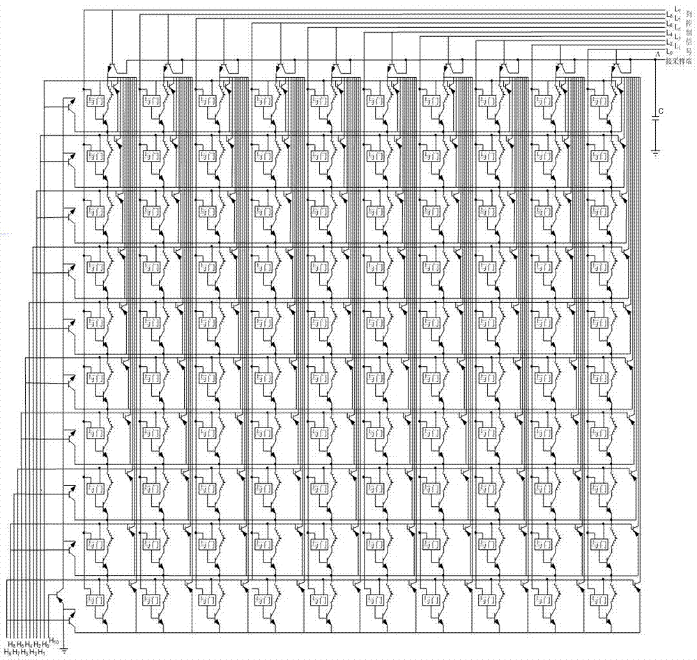
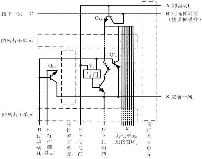
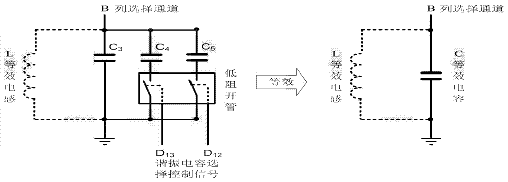
[0022] Such as figure 1 , 2 with image 3 As shown, a passive array magnetic induction antenna device includes a substrate, on which a drive circuit, a voltage stabilizing circuit, a resonant sampling circuit and a plurality of magnetic induction subunits are arranged, and the plurality of electromagnetic induction subunit arrays are evenly arranged, denoted as M *N column matrix, then the drive circuit includes a total row drive circuit, an M row drive circuit, an N column drive circuit and M*N AND gate circuits, and the magnetic induction sub-units correspond to the AND gate circuits one by one; the row total The drive circuit, the M row drive circuit and the N drive circuit are all NPN transistors, the electromagnetic induction sub-unit of each row is corresponding to a row NPN transistor for driving, and the electromagnetic induction sub-unit of each column is corresponding to a column NPN transistor for driving, The row total drive circuit is a row total drive NPN trans...


PUM


Abstract

The present invention discloses a passive type array magnetic induction antenna device. The passive type array magnetic induction antenna device comprises a substrate; a driving circuit, a voltage stabilizing circuit, a resonant sampling circuit and a plurality of magnetic induction sub-units are arranged on the substrate; the plurality of electromagnetic induction sub-units are arranged uniformly in an arrayed manner; the driving circuit includes a line total driving circuit, M line driving circuits, N column driving circuits and M*N AND gate circuits; and the magnetic induction sub-units are in one-to-one correspondence with the AND gate circuits. According to each pair of coils, two orthogonally distributed 10mH inductors are connected in series to form a matrix array; the coils are fixedly welded onto the substrate through two wire terminals; the substrate can serve as a fixing plate for the coils and can also converge and connect the connection lines of each coil to a socket, and therefore, the coils can be installed at the front of an unmanned aerial vehicle; whether a power transmission line exits can be induced in real time through the passive array inductance coils, and the distance information and position angle information of the aircraft relative to the power transmission line can be further induced; and a basis for discrimination can be provided for a follow-up signal processing circuit.

Description

technical field [0001] The invention relates to the technical field of automatic detection of aircraft line inspection in the power transmission and distribution industry of a power system, in particular to a passive array magnetic induction antenna device. Background technique [0002] At present, the maintenance, inspection and emergency repair of transmission lines by power companies are still basically divided into sections, relying on manual on-site inspections of line inspections. The timeliness and accuracy of line defect discovery depend on the professional ability and responsibility of line inspectors and the implementation of inspection and inspection by team managers, and the occurrence of various accidents caused by insufficient inspection cannot be eliminated. At the same time, some transmission lines are erected in deep forests, wetlands, and high mountain areas. The arrival of personnel is slow, difficult, and inefficient. It is impossible to perform regular i...

Claims


Application Information

Patent Timeline
Patent Type & Authority Applications(China)
IPC IPC(8): G01V3/165G01C21/20G05D1/12H01Q1/38G01R31/08
CPCG01C21/20G01R31/085G01V3/165G05D1/12H01Q1/38
Inventor 陈建明郭香静赵明明白磊王成凤崔羊威马跃涛芦杜阳李秦月候青青李军
Owner NORTH CHINA UNIV OF WATER RESOURCES & ELECTRIC POWER
Why Eureka
Try Eureka