
Shooting device

A technology of a shooting device and a casing, applied in the field of drones, can solve the problems affecting the use of drones, limited battery power supply, etc., and achieve the effect of avoiding shooting blind spots and lasting and stable power supply

Inactive Publication Date: 2017-06-27
SHENZHEN DINGCHUAN XUFEI TECH CO LTD
View PDF7 Cites 2 Cited by
  • Summary
  • Abstract
  • Description
  • Claims
  • Application Information

AI Technical Summary

Problems solved by technology

[0002] For shooting needs, people usually install cameras on drones for high-altitude shooting. However, drones usually control the flight of drones through rotors, and the existence of rotors has a certain blocking effect on cameras. The maximum shooting angle of the camera on the drone is only 180 degrees, and there is a shooting blind spot
And the current drones are usually powered by a simple battery. However, the battery power supply is limited and cannot provide a relatively long-lasting working environment for the drone, which directly affects the use of the drone.

Method used


Image

  • Shooting device
  • Shooting device
  • Shooting device

Examples


Embodiment Construction

[0025] In order to facilitate the understanding of the present invention, the present invention will be described more fully below with reference to the associated drawings. Preferred embodiments of the invention are shown in the accompanying drawings. However, the present invention can be embodied in many different forms and is not limited to the embodiments described herein. On the contrary, these embodiments are provided to make the understanding of the disclosure of the present invention more thorough and comprehensive.

[0026] It should be noted that when an element is referred to as being “fixed” to another element, it can be directly on the other element or there can also be an intervening element. When an element is referred to as being "connected to" another element, it can be directly connected to the other element or intervening elements may also be present. The terms "vertical," "horizontal," "left," "right," and similar expressions are used herein for purposes ...


PUM


Abstract

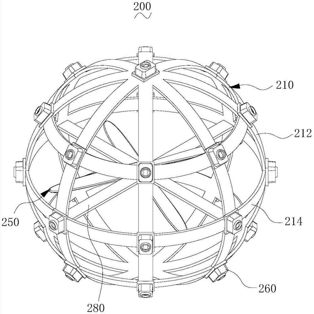
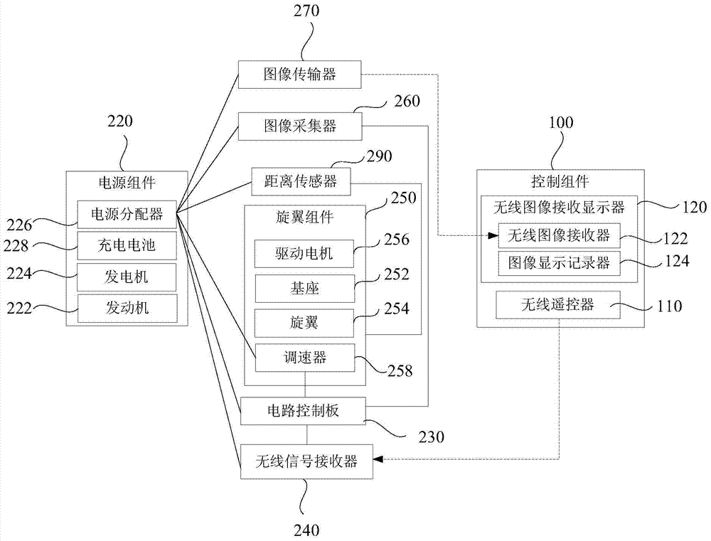
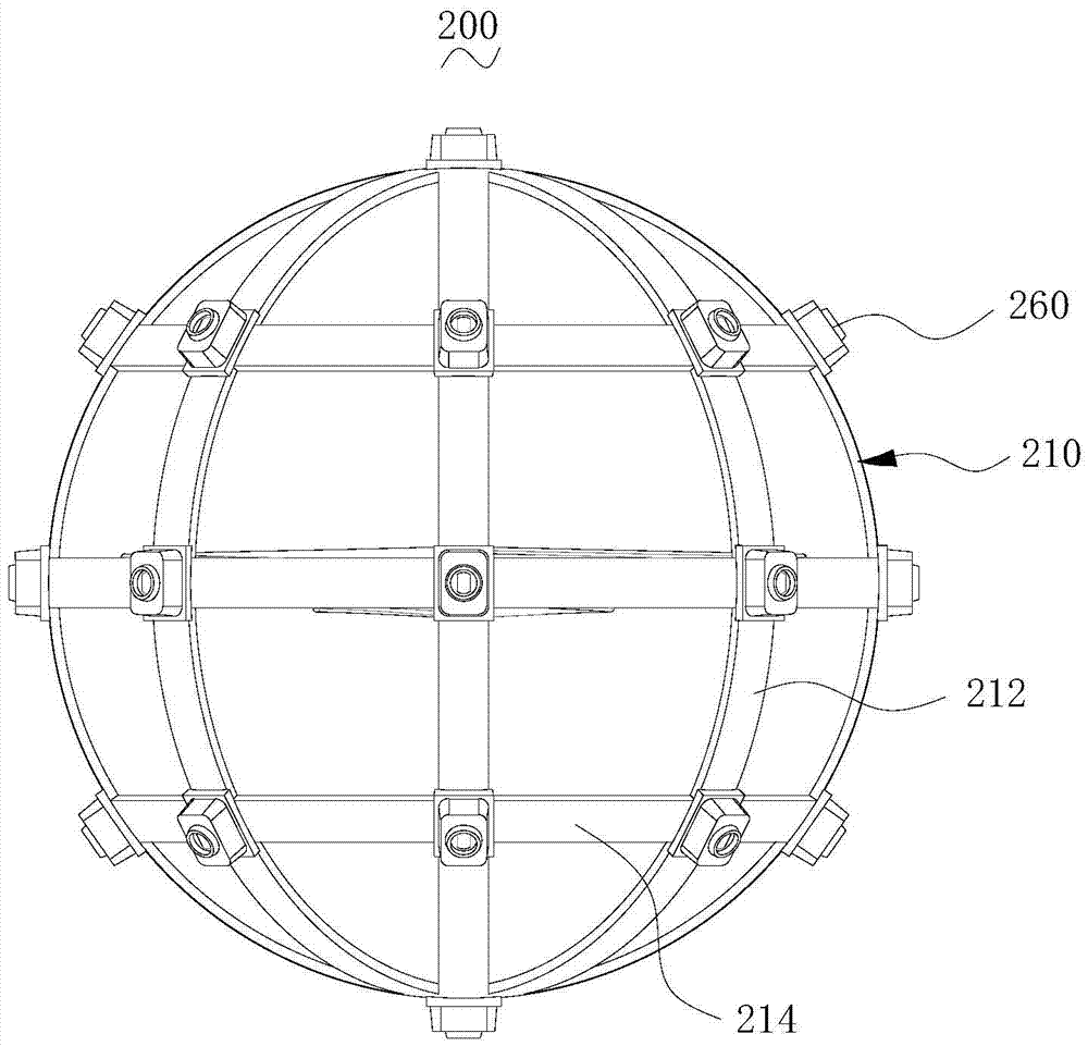
The invention relates to a shooting device. The shooting device comprises a control assembly and a flight part, wherein the control assembly comprises a wireless remote controller and a wireless image receiving display device, and the flight part comprises a housing, a power supply module, a circuit control board, a rotor wing component, image collectors and an image transmitter; the housing is a hollow sphere, and the power supply module, a wireless signal receiver, the rotor wing component and an image transmitter are all contained in the housing; a generator of the power supply module is arranged on an engine and a power distribution unit is electrically connected to the generator; the circuit control board, the wireless signal receiver, the rotor wing component, the image collectors and the image transmitter are all electrically connected to the power distribution unit; the image collectors are used for collecting images and transmitting the images to the image transmitter, and the image transmitter is used for transmitting the images to the wireless image receiving display device. According to the shooting device, the more durable and stable power is guaranteed to be supplied to the flight part and the shooting part can shoot at 360 degrees without a blind area.

Description

technical field [0001] The invention relates to the field of unmanned aerial vehicles, in particular to a shooting device. Background technique [0002] For shooting needs, people usually install cameras on drones for high-altitude shooting. However, drones usually control the flight of drones through rotors, and the existence of rotors has a certain blocking effect on cameras. The maximum shooting angle of the camera on the drone is only 180 degrees, and there is a shooting blind spot. And the current unmanned aerial vehicle usually adopts simple battery to supply power, yet, pure battery power supply is limited, can not provide comparatively lasting working environment for unmanned aerial vehicle, has directly influenced the use of unmanned aerial vehicle. Contents of the invention [0003] Based on this, it is necessary to provide a shooting device with relatively durable and stable power supply and no blind spots for shooting. [0004] A photographing device, compris...

Claims


Application Information

Patent Timeline
Patent Type & Authority Applications(China)
IPC IPC(8): H04N5/232H04N5/247H04N7/18B64C39/02B64D27/24H04N23/90
CPCH04N7/181B64C39/02B64D27/24H04N23/661H04N23/90B64U10/10B64U50/19B64U2101/30Y02T50/60
Inventor 范首东
Owner SHENZHEN DINGCHUAN XUFEI TECH CO LTD
Learn More